Laser Welding Basics – Part 3
12 Minute Read
Back when I was going to school, if I had known I would be writing an article about laser welding geometry I would have paid more attention in all my math classes, not to mention my English composition classes. We aren't going to be figuring any geometric theorems in this article discussing the geometry of laser welding with lower energy . In fact, all of this geometry is so simple that it will be common sense when I'm finished. Of course, that is, only if I can write it in proper English for you. My best grades were in metal shop and Physical Education.
Geometry of Laser Welding with Lower Energy
On the machinery sales side of my business, we boast about how short the learning curve is with a laser welder. To become productive and get a return on investment from a laser welder in our industry the learning curve is short. However, I have been working with the laser for almost 5 years and I am still learning. The laser welding machine is a very simple device in it's function, but as with all machines and tools, it can accomplish much more with an operator who has an intuitive instinct to learn, combined with the will to put that learning into practice. I say that because much of what I am writing about in this article requires certain hand-eye coordination that, after laser welding for 5 years, I find I am still finding ways to improve.
I chose "Welding with Lower Energy" for this article because of my own experience with laser welding. Lower energy laser welding is not really relevant unless, like me, you have been welding with too much energy. In my experience, I have found that as I learn more about what a quality weld looks like, and how to better accomplish those results, my energy parameters started decreasing. The same work is being accomplished, with lower total energy. The highest quality weld that can be achieved is a joint that has been welded to achieve adequate penetration, fusion that is uniform and free from voids, and accomplished at the lowest amount of energy that will get the job done right. You may recall from my previous articles, total energy is determined by a combination of the adjustable Voltage and Pulse Duration Parameters, where as the adjustable Beam Diameter is the physical area that the total energy is concentrated into. Welding with lower energy, or perhaps better said: "welding with the correct energy", is important and advantageous to the operator for many reasons.
A single weld spot from one laser pulse on a piece of metal, although on a smaller scale, canbe compared to melting alloy in a crucible. Anyone who casts, makes their own alloy, or simply melts pieces down to re-mill, knows that melting for too long with too high heat will start burning metals out of the alloy. The initial appearance when welding with too much energy, to the inexperienced eye, can be as deceiving in welding as over heating can be in casting. Higher heat in casting, up to a point, can result in better form filling in the investment. However, micro sponge-like porosity is often the result from metal that burnt and vaporized out of the alloy because of too much heat. Too much energy when welding can cause the metal to flow with ease, but you may then find the same micro porosity through the weld seam that is often the same result as casting with too much heat. There are many variables when selecting energy parameters for welding specific metals and their alloys that I intend to address more specifically in later articles.
Low energy welding is a great benefit when welding close to heat sensitive items such as gemstones, small spring tempered findings, fine filigree, engraving, hollow or thin items. For these kinds of welding jobs there are a host of techniques and innovative products that continue to increase the productivity that laser welding has to offer in our industry.
By the way, the micro laser welding techniques that we are using on jewelry are nothing new in regards to the subject of welding itself. We are not re-inventing the wheel. If you ever have a chance to pick up a welding journal, or trade publication dedicated specifically to welding, you will find them full of the exact kind of information I am writing about here, only specific to a particular industry or type of welding. Welding is welding, and understanding the basics allows us to go further and get more specific about both the type of welding materials being welded, and techniques related to each.

Before we go further, lets take a quick look at a basic function of welding known as drawing a bead. In welding terminology, a continuous weld seem is known as a 'bead'. Making a continuous weld seam is referred to as drawing a bead. Pulsed Yag welding lasers like the ones being used in the jewelry industry simplify drawing a bead by allowing the operator to adjust pulse frequency. This feature allows the operator to hold down the foot pedal while the lasers preset parameters continue to pulse at a timed rate set by the operator.
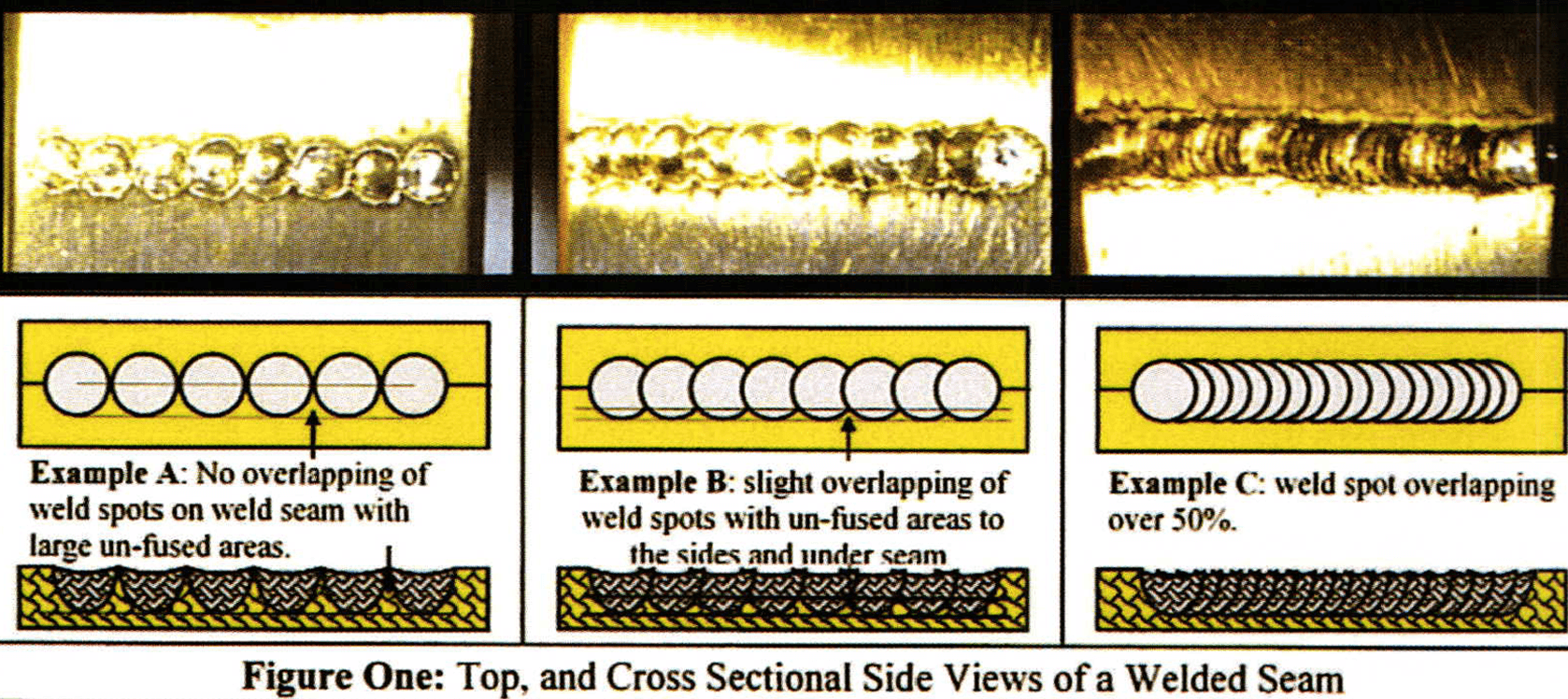
When drawing a bead, it is important that the operator controls movement of the piece through the focal point of the laser beam, at a coordinated pace with the set pulse frequency so that the individual weld spots are correctly overlapping. A combination of the uniform overlapping of weld spots, correct energy parameters, and as we will discuss in a moment, correct angle, will ensure that important areas within the seam are fused. Figure one shows three examples ofweld seams, with top views and cross sectional side views of the individual weld spots over the length of the seam, and how the spots come together to form a bead.
Example A cannot really be called a bead, because the spots do not overlap. Rather, Example A is a series of individual spot welds that are placed side by side on the weld seam. From the top view of Example A, the operator may think that the seam is being adequately fused because the line of the seam will disappear from the top, providing that the weld spots fuse together at the top of their circumference. From the cross sectional side view of Example A, inside the seam, one can see that the slightest bit of filing, sanding, or finishing from the top of the seam will expose un-fused portions of the seam.
Example B, of Figure One, shows some overlapping of the spots in the bead, but weak, un-fused areas will still exist because the overlapping is not as sufficient as it could be if the weld spots were overlapped as shown in Example C. The overlapping of the weld spots to form a bead is accomplished by controlling the relationship between the rate that the weld seam moves through the focal point of the beam and the pulse frequency of the laser. This is a very basic adjustment to make. But, because jewelry is almost always being held by hand when welding, this adjustment requires the operators hand-eye coordination combined with his or her knowledge of a quality bead.
Because jewelry has numerous angles, curves, and design features it is usually necessary to hold a piece by hand when welding. Welding angle is as important as selecting the correct laser parameters to complete a job. In my experience with laser welding, as well as in my experience training people how to laser weld, I have noticed that it is difficult to use the optimum welding angle based on simple knowledge. Rather, I have noticed that angle adjustment becomes an intuitive instinct of the operator who has some practice. In most other industries that use laser welding, it is easier to demonstrate optimum weld angle because many industries are setting up their weld jobs on an automated system where it is only a matter of pre-positioning the holding device to achieve the best angle. With the geometric features and complexity of jewelry design, automated handling of the piece during welding is rarely ever possible.
Because of the agility that jewelers gain through their experience in welding by hand at various angles, combined with the knowledge of the machines adjustable parameters that results from welding so many different types of alloys and metals from thick ring shanks to fine prong tipping, jewelers are among the very best operators of this technology that I have seen. As ones' hand/eye coordination becomes accustomed to the machine, and the knowledge and experience regarding quality welding grow, an operator can achieve results on a given piece with a lower energy, simply by using different angles. There are as many examples of angle manipulation as there are jewelry designs. Perhaps one of the best ways to demonstrate angle and energy requirements is in relationship to drawing a bead with filler wire.
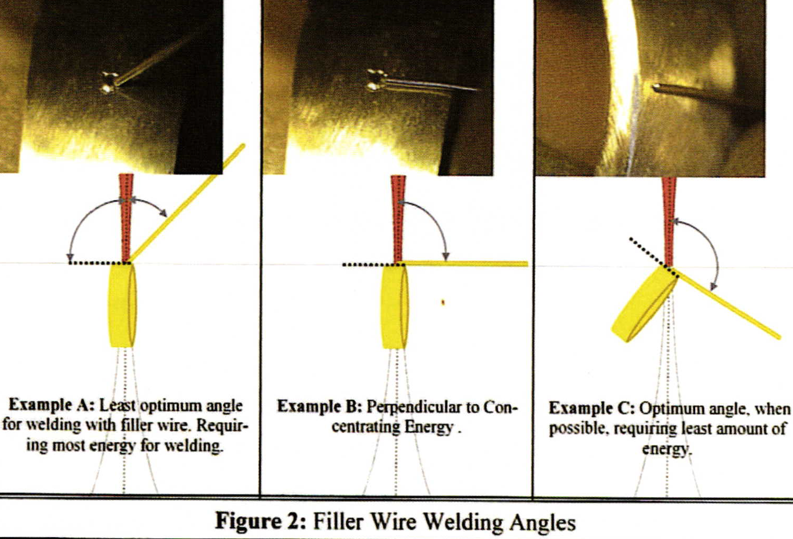
When drawing a bead with filler wire lower energies can be used with altered angles. Altering the angle to optimum is not always possible, depending on design features of the piece and where on the piece, the welding is being performed. Figure 2, Example A shows the welding wire at an acute angle to the concentrating beam. An angle like this requires enough energy to melt through a larger mass of wire and into the piece. The amount of wire being exposed to the beam is referred to as, "Wire Feed Rate", and, in our case as jewelers, is usually controlled by the operator, who is holding the piece and the wire by hand. With A's acute angle, the feed rate is much more difficult to control, resulting in larger volumes, as well as inconsistent volumes, of wire being subjected to the beam.
The acute angle of Example A's wire also has a tendency to reflect the laser away from the intended weld spot. Example B's wire angle makes the wire feed rate easier to control. B allows the smallest bits of wire volume, as well as consistent lengths of wire, to be nibbled off by the beam at the operators will. However, even if B's feed rate is controlled to melt only a fractional length of wire, B still requires the laser energy to melt through the wires entire diameter before fusing into the piece. B's wire angle, although not as extreme as A's, can also have a tendency to reflect the laser light away from the weld spot. The optimum angle is shown in Example C because, just like B, the feed rate is easy to control, and the focal point of the laser beam is able to nibble off a very small piece of the wires face rather than having to pass through the entire girth of the wires diameter.
A laser is a beam of light. The machine amplifies that light, and it puts all of the beams light into the same wavelength making the light very predictable, comfortable, focusable, and suitable to use for welding. However, various physical circumstances such as metals with different heat conductivities, and the reflective, polished, or shiny natures of different types of metal, at altered angles to the beam when welding, can create resistance to the light beam. This resistance acts much like a mirror when pointing the beam of a flashlight into it. The beam of light reflects. After reflecting, the light becomes scattered and as it dissipates it loses its effectiveness for welding, not to mention that it is now traveling in the wrong direction, away from the weld spot. Increasing total energy, or increasing the energies concentration into a smaller beam diameter, are ways to overcome reflectivity by changing the machines adjustable parameters. There are other techniques for overcoming reflectivity that I will write about in up-coming articles. However, if the machines parameters are close to being correct for the job at hand, altering weld angle is one of the most convenient techniques to overcome reflectivity.
There are also products available on the market that are enabling lower energy welding. The reason why can all be explained with very simple geometry.
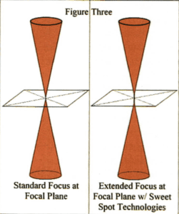
Sweet Spot Technologies that are available, as options, in some lasers, as shown in Figure 3, provide a finer focused beam over the focal plane. The diameter of the beam stays consistent for a distance above, through and below the focal plane. The physical force of the laser beam straightens out and enters the metal as a good Olympic high diver would enter the water: very straight and uniform, causing no splashing, and minimal turbulence. This effect allows the operator greater ease in creating uniformed, overlapping weld spots throughout the bead at lower total energy. This provides consistent energy distribution, and concentration for a nominal distance above and below the focal plane, giving the operator an area of grace to move the piece by hand and keep consistent results, regardless of slight movement above or below the focal plane. The energy concentration in the physical outline of the focused beam is better described in my last article.
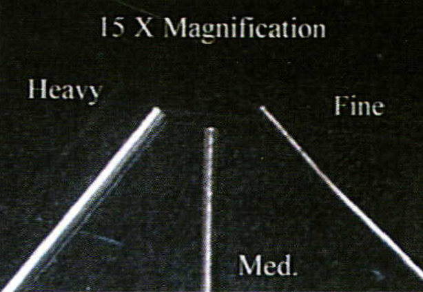
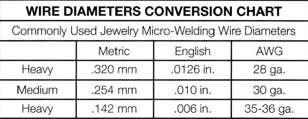
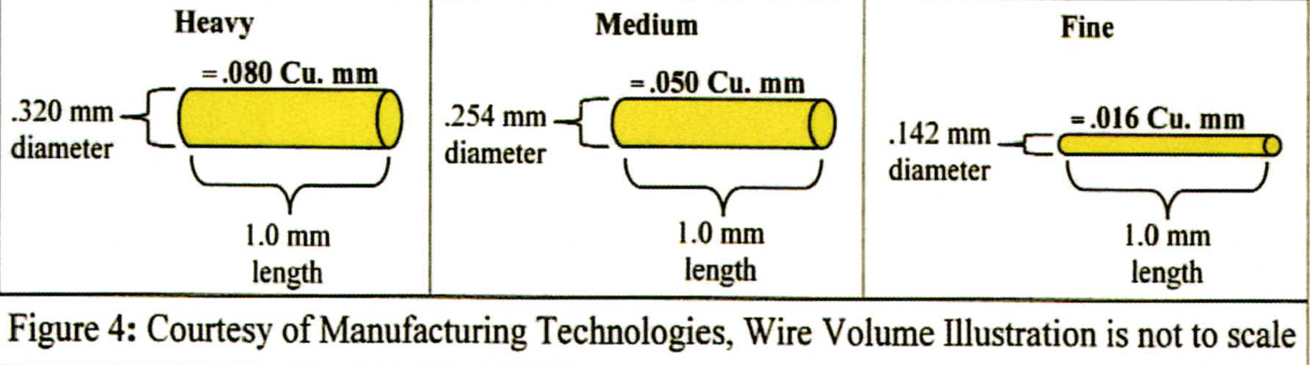
When thinking of the laser's energy requirements in connection with filler wire, consider that the beam must have enough energy to melt through a section of filler wire into the piece. The more mass, or volume, of wire that the beam must melt through, the more energy will be required. Wire volume being melted, can be controlled by wire feed rate as discussed earlier in this article, but it can be further controlled by the diameter of wire being used. Each diameter used has its function depending on the job at hand. Figure 4 shows examples of commonly used filler wire diameters with the volume of a 1 mm length of each wire diameter. The smaller diameter wires allow lower energy parameters to be used with greater ease of welding thin materials, or close to small or heat sensitive items with less risk of melting through, or causing damage to these items.
We are working our way through the basics in this series of articles. I hope you will stay tuned for the next article, as I plan to continue the discussion about recognizing a quality weld in relationship to selecting parameters for a given job. As I continue, I will be using more specific examples ofjewelry items being welded. You may find it useful to read my previous articles in Bench, as this one is intended as part of an on going series that includes those articles. Back Issues of Bench Magazine are available at www.BWSimon.com/Bench or you can find the articles on my web site at www.mantech.info. The Home Page has a link to Trade Publications. You can also call or e-mail me for copies at (619-239-5842), (lasers@mantech.info).
See Also:
Laser Welding Basics - Part 1
Laser Welding Basics - Part 2
Laser Welding Basics - Part 4
Related Articles
Benchtop Hydroflux Welders

Etype Automated Wax Injection System

Goldsmithing: Fusing Technique

Master Metalsmith John Prip


The All-In-One Jewelry Making Solution At Your Fingertips
When you join the Ganoksin community, you get the tools you need to take your work to the next level.
