Laser Welding Basics – Part 4
13 Minute Read
I want to take what I have written in my previous articles and start tying it into jewelry welding applications. In this article, I am going to use the welding of a very simple 18K yellow gold ring shank to expand on the relationship of the lasers primary adjustable parameters.
The Basics of Laser Welding Proportions and Effects
In all of the laser welding training that I do, I refuse to give out pre-set parameters for given metals and jobs for a couple of reasons. First of all, I do not like to give people a crutch when they can easily learn to walk. Secondly: Every machine will react slightly different from another. Therefore, I spend my training time teaching operators the principles of welding, the characteristics of the individual parameter effect, and how the multiple parameter effects relate to one another. Hopefully, when finished, one can judge for themselves.
If you would like a copy of the previous articles in this series, you can go to www.mantech.info and get them under Trade Publications. You can e-mail me at lasers@mantech.info, or call me at 619-239-5842. They are also published in subsequent issues of Bench Magazine.
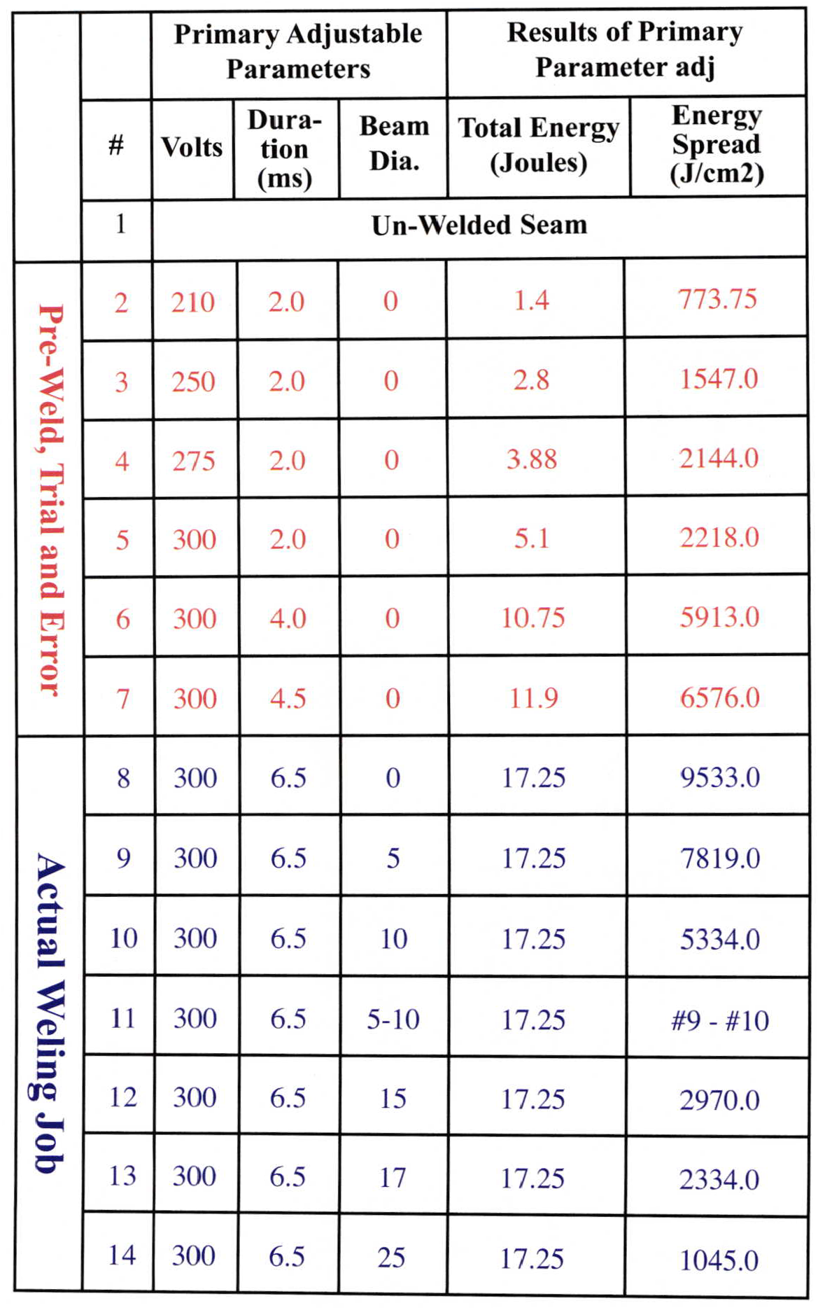
The following illustrations show a 2.5 mm thick, 18K yellow gold ring shank that has been cut and fit so that the seam is closed, as if it were being prepared for soldering. On this particular ring we will weld it exactly as it appears here, without changing the joint design, or previously adding anything to the joint. There are also other techniques for accomplishing this type of job.
There are circumstances when it is better to remove metal from the joint, such as creating a 'V' groove, or simply cutting approximately 2/3 of the way through the joint before welding. On an 18K yellow gold ring shank, this is rarely necessary unless the seam being joined is very close to a delicate design feature or a heat sensitive stone. In that case the purpose of removing material from the joint would be to allow the seam to be joined at a much lower total energy by a series of back filling the joint operations with filler wire. The back filling process is simply drawing beads with filler wire in the section that has been cut away. Drawing a bead with filler, can be accomplished at a much lower energy that will put surrounding sensitive items at much risk from radiant heat and laser reflections.
Penetrating and fusing into the joint without removing metal will require more energy than the removal and backfill technique, because resistance from existing metal in the joint must be overcome with higher energy. Higher energy requirements for welding our joint design brings me to another reason why one may consider removing material before welding. If this ring were made of an alloy such as nickel white gold, containing metals such as nickel or zinc that can vaporize or crack with too much concentrated heat, one may consider removing metal from the joint, and back filling at a lower total energy.
There are other techniques forwelding nickel white gold that involve technology such as customized pulse shaping features that I will discuss in another article. Standard 18K yellow gold, as long as it is not contaminated with solder, reacts very well to higher total energy. Some people like to add a wafer of metal inside the seam that protrudes slightly out of the seam. This technique, if done properly, can reduce the amount of back fill that is necessary. Personally, I would rather backfill, than spend my time preparing a thin wafer for every seam that I weld.
If you recall my previous article about the specific parameters, total energy (expressed in Joules), is determined by a direct relationship of both voltage, and (pulse duration, usually expressed in mille-seconds). Voltage and duration are the energy parameters. Total energy has two characteristics that must be balanced in reasonable proportion for a given welding task. A common mistake that many beginners make, (I was included), is to work at a given duration for most jobs, and adjust voltage only. I hope this article will show how to balance the two energy parameters. It is very useful to have a calculated total energy display, (Joule Meter), built into the welding machine display unit, such as the Rofin that I am using. I find that the Joule Meter is very useful to help understand the relationship of the two energy parameters, as one examines the result of a given weld. That is exactly what we are going to do right now.
Before we determine how much energy, and the proportion of the two energy parameters for this job we must determine what size of a space we will concentrate that energy into. Since the seam is closed and tight fitting, we will start this process with the narrowest beam possible. We will be penetrating and fusing through 2.5mm of 18K yellow gold so the narrower the beam, the lower total energy we will need to penetrate and fuse. If you recall from a previous article, we are welding with light that is being focused down to a selected diameter through a lens.
Have you ever played with a magnifying glass in the sun? Have you ever started a fire that way? If you pick a focal point and focus the sunlight through the magnifying glass down to a very narrow diameter, at that focal point, the energy of the sun becomes very concentrated. The total energy at the glass is the same as the total energy at the concentrated focal point. However, there is more energy per square area at the focal point. That makes the energy aggressive in a small space where it can accomplish some work, like starting a fire, or in the case of the laser, penetrating and melting metal. I find that it is also very helpful to understand parameter relationships if you have a meter on the machine's display that shows the calculated energy concentration over a particular area, (Joules per sq. cm). We will start with the narrowest beam. The Rofin laser I am using has a beam diameter range of .2 mm -2.0mm and has forty-two adjustable increments within that range. These increments are expressed in arbitrary numbers, 0-42. We are starting with a beam diameter of 0.
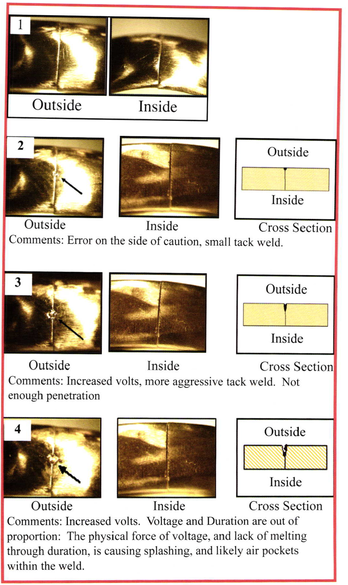
Since our beam diameter is decided for now, we must figure out what our energy settings should be. We are going to start a trial and error process as if we are beginners. Therefore we will start at a safe energy and work up. The energy settings on the laser that I use range as follows: (voltage 190-450), (duration 0.5 ms-50.0 ms). The result we are trying to achieve, for this particular example, is 100% penetration through the ring shank with good melting effect all the way through. When I am doing such a job in my shop, I don't go through all of these steps, and usually do not try to achieve 100%o penetration from one side of the shank.
However, when I am training a beginner I go through this exercise because it really shows the parameter relationships at work. We will be examining the effect of the weld spot from both sides of the seam to determine the correct proportion of the two energy parameters. Please follow the results on the attached chart and illustrations. Again, it is normally not necessary to go through so many steps of trial and error to find the right energy for such a job. We actually went a little further than necessary just to see the visual effects of how the parameters relate. We also went through quite an effort to get the perfect proportion between the two energy parameters. I hope to show you that the adjustable beam diameter is one of the most important parameters in the whole process.
Using various diameters allows us to use the same energy, but focus that energy into a different sized concentrated area. It gets back to the magnifying glass example. By having the ability to spread the energy out, or further concentrate it, we can be a little less concerned with having the perfect proportion between our energy parameters (volts and duration). For example, we could have completed this job with our trial and error examples 5-8 just by using various beam diameters. Each one of examples 5-8 would have looked different throughout the finishing stages of the job, but it would be possible. Since adjusting beam diameter plays such a large role in the jobs completion, I hope you will see, that the more adjustable increments you have within the range of beam diameters available, the more control you will have over the work you are performing.
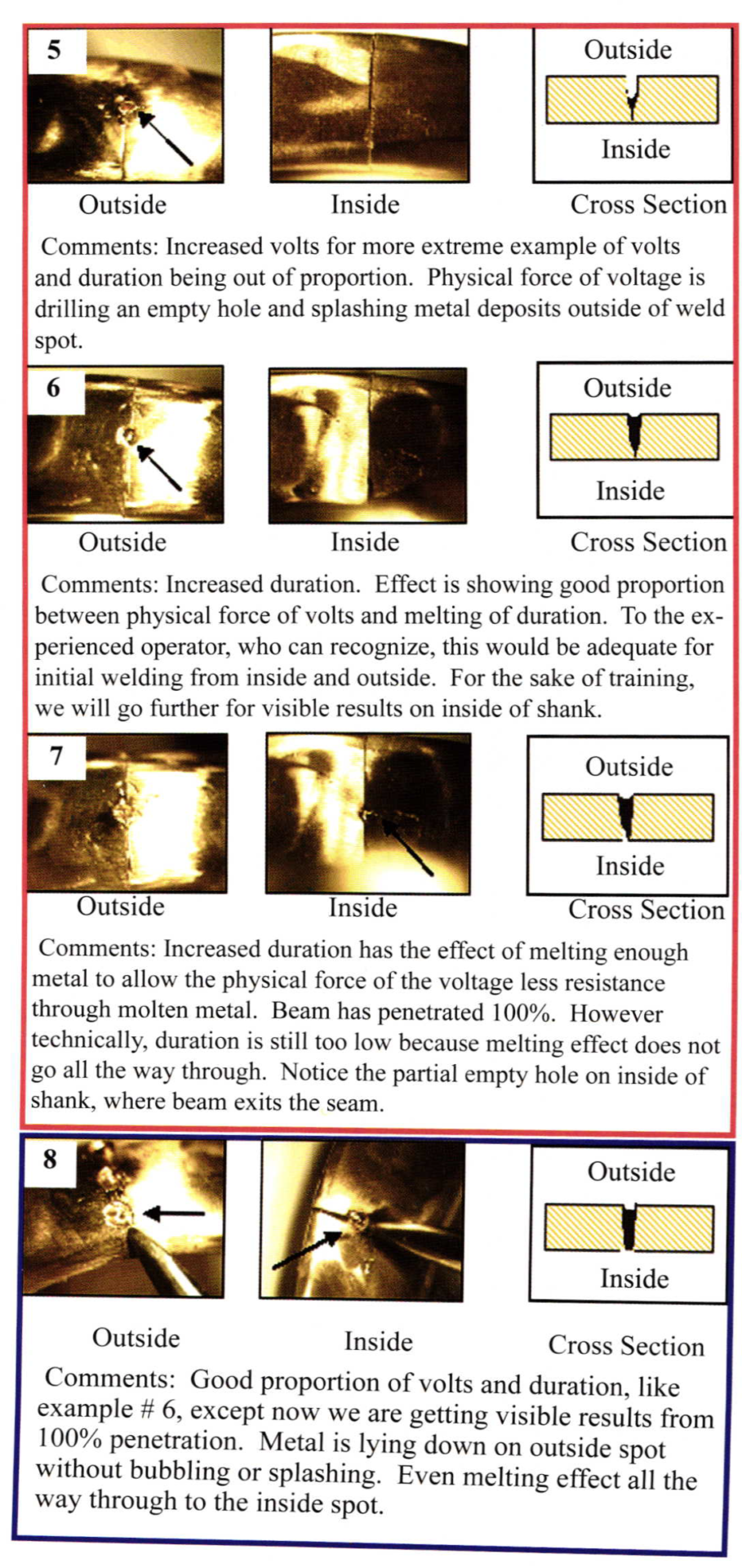
In my comments, I mentioned that example 6 would have worked very well for the operator who is experienced enough to sense what kind of penetration and melting actually occurred. We humans do not have X-ray vision, so it is difficult for the beginner to know that example 6 would be adequate. However, we humans do have some other senses that, with some attention, experience, and some knowledge gained through articles like this, can give us indications of what is happening inside the metal. The laser light is physical matter that we can hear when it hits the metal. We can also feel a slight vibration. Attention to the details of your senses will help you better determine what is happening. Through reading books written by laser welding engineers, I have learned a new term for what is happening in examples 6,7, & 8. It is called, "key-holing".
A key is not effective in its function unless it fits perfectly as it was intended to fit. In our welding we must work not only to create the hole that gets adequate penetration, but also to create the key that fills the hole back up without voids. The better we get at dialing in the correct proportion ofour energy parameters, the better we get at key-holing. As long as we are not creating air pockets and voids within the weld, we can adjust for imperfect keyholes by using our energy spread capability, through the beam diameter adjustment.
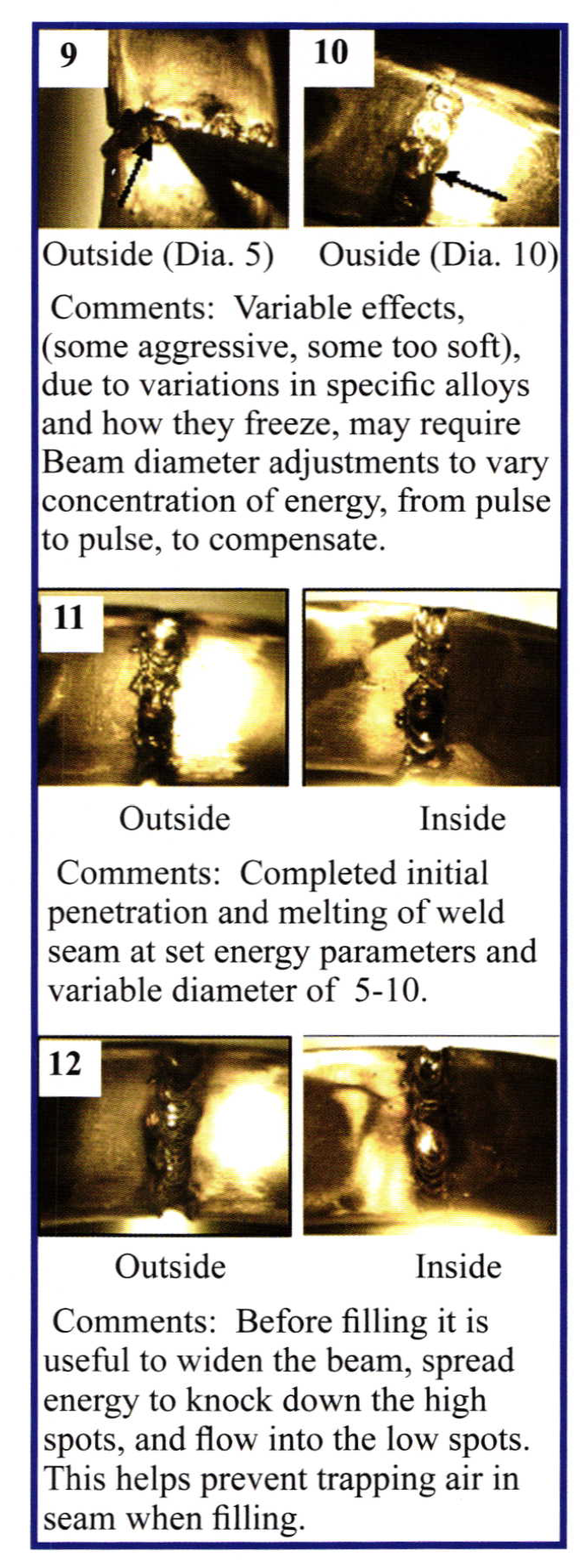
Since we have the ability to weld this shank from the inside and the outside, example 8 is a little too much. However, since we went through all the effort to make such a well proportioned keyhole, we aren't going to back off with our energy parameters. Rather, I am just going to spread the energy into a wider beam in order to decrease penetration to 60-70%. Then we will weld a bead over the seam from all angles around the shank. In my last article, I wrote about the importance of overlapping spots. Remember our keyholes are actually like little melted crucibles in the seam. We do not want to leave any open or un-fused areas within the seam, so we overlap.
Here is a critical point that I must talk about. As we weld the seam, we will notice that the effect from one laser pulse may be different from another laser pulse. This has a couple of causes, and will vary depending on what type of metal or alloy we are welding, as well as the state of the metals grain structure when we are welding it. If we are welding at a slow pulse frequency, the difference in effect from pulse to pulse will be more noticeable. There is nothing wrong with the laser.
However, each key hole we make will freeze with various outward characteristics from one another. One may freeze with an extremely reflective surface that reflects portions of energy of the subsequent, overlapping pulse away, rather than letting it penetrate. Another may solidify with a matt finish, thus allowing the subsequent pulse to really penetrate hard with more aggressive results than when we started. I have also noticed that quality mil products weld much more evenly from pulse to pulse than most cast products.
My thought on that subject is that the grain structure of the metal is more consistent in the mil product. Cast products can have various grain structures throughout, due to various cooling rates after casting. There are a couple remedies for these inconsistent pulse to pulse effects. One remedy is to increase pulse frequency to be fast enough so as to prevent the previous keyhole from solidifying before bombarding the overlapping area with the next laser pulse. When using faster frequencies, one may need to decrease the total energy, or widen the beam, because keeping the energy exposed more frequently will have an overall more aggressive effect. Also, when pulsing too fast, if you are not careful, you can start to burn metals out of the alloy.
Burning metal is more prevalent in some alloys over others. The best way to compensate for inconsistent effects from pulse to pulse is to pay attention with your senses, and when the effect is too aggressive, start widening the beam; if the effect is not aggressive enough, start narrowing the beam. Spreading and concentrating the energy in this fashion may even be necessary with faster pulse frequencies, depending again on the metallurgy of the piece being welded. Again, the more incremental control that your machine has built into its beam diameter adjustment, the better inconsistencies within the metal being joined can be controlled in the welding process.
The more attention that is paid to dialing in the correct proportion of energy parameters, the less filling that will need to be done. Even with proportional energy, there is usually some filling required to re-establish the geometry of the pieces design lines and contours. At this point I find it helpful to simply spread the energy out a little more by widening out the beam and smooth the seam before filling. This will knock down the high spots and fill in the low spots. This step is not always necessary but it helps prevent air pockets from developing while drawing a bead with wire during the filling process.
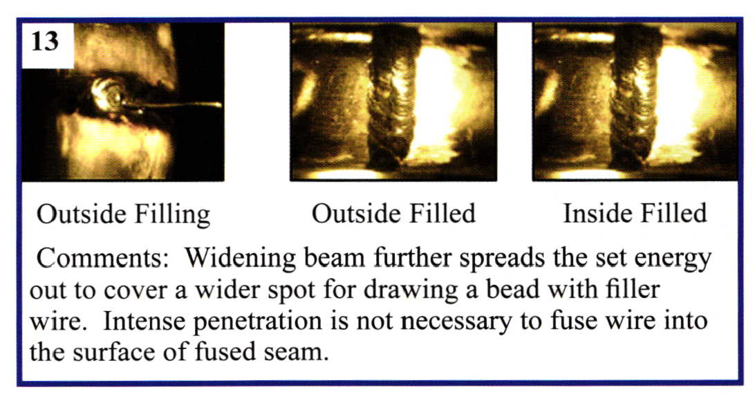
When filling with wire, the key-holing that we where accomplishing back in steps 8-11 is no longer required. We only need to fuse the wire into the surface of the seam. For this I find it particularly handy to keep the same total energy, but simply spread it a little wider. By keeping the energy at the same level as when we were key-holing we can widen the beam out enough to cover all or most of the effected area and fill with less passes than if we used a lower total energy. It is also extremely easy to simply reach over and bump the machines beam diameterjoystick, a few times, and go to work filling. In my last article,
I wrote about welding angles when drawing a bead with filler. The amount that we can widen the beam for filling will depend on how well we can get the wire to fuse into the surface of the seam with a given energy spread. If the filler material starts to ball up on its end, the operator may be able to get it to flow by altering to a more optimum angle. If the wire still does not flow after using a better angle, then the beam is likely too wide, and needs to be concentrated by slightly decreasing beam diameter.
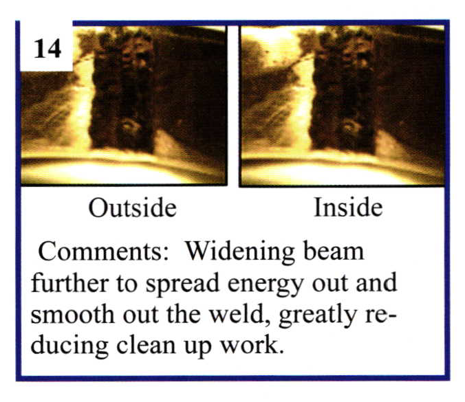
When we get really good at drawing beads with filler, and using optimum angles, a nice smooth bead can be made that requires little more. However, if we desire, we can make the weld look even prettier, and possibly reduce the amount of clean up at the bench by spreading the energy even wider and going over the bead to smooth it out even further.
I should mention that we used a secondary parameter called pulse frequency. This allows for the successive, automatic firing of laser pulses at a pre-set rate. The Rofin I was working on cycles from 0 to 20 pulses per second. Pulse frequency is selected at the comfort level of the operator, and can be helpful in keeping the action going.
The main thing that I want to draw your attention to is what I have been harping on all along, (BEAM DIAMETER). You can look at the chart of parameters for this job, and see that once we get our energy even close to the correct proportion, we can accomplish the rest by controlling the concentration of energy through beam diameter. The more adjustable increments that you have in your range of diameters, the more control you will have in spreading the laser energy.
See Also:
Laser Welding Basics - Part 1
Laser Welding Basics - Part 2
Laser Welding Basics - Part 3
The Best Laser Welders: Reviewed
Related Articles

Platinum Jewelry Advanced Joining Techniques

20 Laser Welding Tips

Faster, More Efficient Laser Welders

Laser Mokume – The Satow Method


The All-In-One Jewelry Making Solution At Your Fingertips
When you join the Ganoksin community, you get the tools you need to take your work to the next level.