
Pulse Shaping Test, 14k Ni WG
8 Minute Read
The following is one method of adjusting parameters after altering the pulse shape. This article is not intended to promote pulse shaping as a means of welding nickel white gold, (Ni WG). More importantly, it is primarily intended as a report on the particular method of pulse shaping that was used here, to incorporate pulse shaping into the welding of 14k Ni WG.
The method could be used for welding other material as well. This project's secondary intent is to test, by the best means available, if greater ductility can be achieved in l4k Ni WG by the use of a particular altered pulse shape. Also discussed are some details that have been helpful to the welding of Ni WG, with or without pulse shaping. A more comprehensive report on welding Ni WG, as well as basic principles of pulse shaping, weld parameter schedules, instructions, and charts is available.
The report contains an informational video as well. Formore details on how to acquire this report, call 619-239-5842 or e-mail lasers@mantech.info. The reader will notice that the following results achieved, by the use of pulse shaping, appear to be in favor of the particular pulse shape (PS) and method used. Please note that the testing procedures used for these documented results are rather crude in comparison to what could be done in a real metallurgical lab.
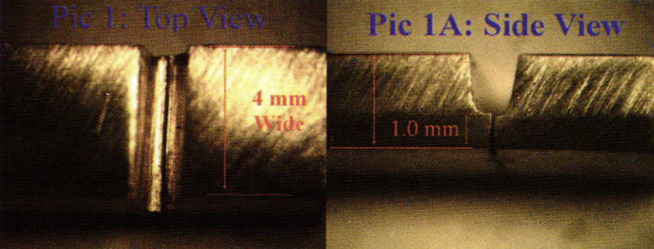
Pictures 1 and 1-A show a piece of 14k Ni WG, medium temper, which is 4 mm wide by 2.5 mm thick. The weld seam is a notched butt joint. The notch is to permit the welding of a thinner section with a lower energy. The reasoning behind having the notched joint is more adequately described in a previous article, titled: "Ni WG Welding". A reasonably tight fitting joint permits a small beam diameter adequate penetration (volts) and melting, (MS), with the least amount of energy. Energy must be balanced (between volts and MS) for the selected beam diameter, so that a solid 60% penetration is achieved from both the top and the bottom of the joint.
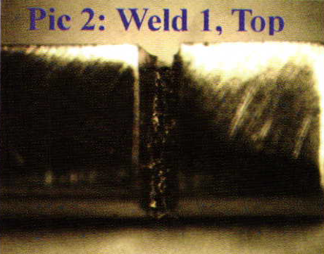
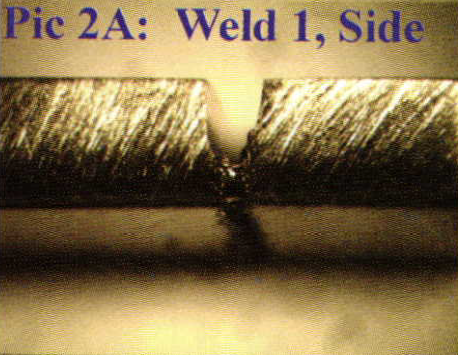
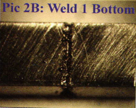
Pictures 2, 2-A, and 2-B show the initial weld. Weld I on The Weld Schedule Chart shows the chosen parameters. For more on determining adequate penetration and melting read the article titled: "Proportions and Effects". Fifty percent penetration with a pulse rate of 0 Hz was settled with volts, pulse duration, and beam diameter.
 |  |
Further penetration is achieved with a faster pulse rate of 5 Hz. A faster frequency with balanced energy minimizes air pockets in the weld from inconsistencies in travel speed and welding angle that will occur when the piece being welded is held in the hand as the vast majority of jewelers must do. However, a faster frequency requires caution that the piece be kept in a steady constant motion so that one area ofthe seam is not over- heated and over worked by too much melting.
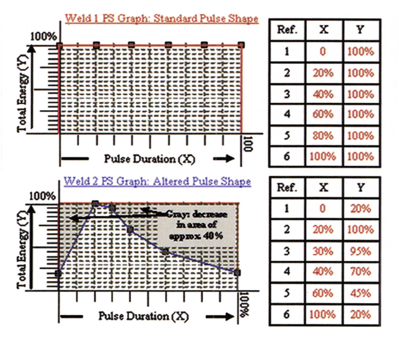
The initial weld that is shown in Pictures 2, 2A, and 2B was performed with a standard pulse shape, (PS). The PS has a direct relation- ship with total energy (J), as well as energy spread (J/cm2). Where as any alteration of the PS from standard by itself will decrease J. and J/cm:.the standard PS allows maximum energy, which is ultimately determined by the balance of volts and duration (MS).
 | |
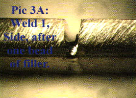 | 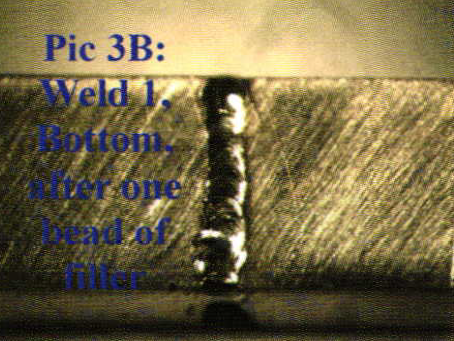 |
Weld 1, Pictures 3, 3-A, & 3-B: After the initial weld, the energy is sufficient to simply widen the beam diameter spreading the 1.55 J into a wider area, (J/cm2), so as to allow a shallower penetration and melting, but wider filling with 30 gauge, (.010″), l8k, Ni WG wire. More about Ni WG filling is discussed in the article titled: "Ni WG Welding".
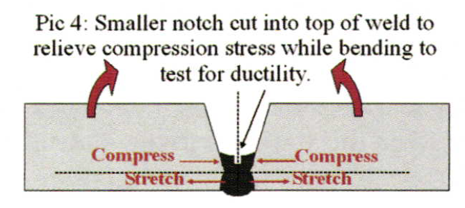
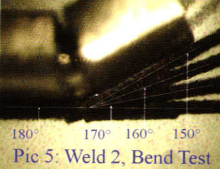
For this project the weld was filed flat, back to a dimension of 1 mm thickness, and then further notched with a saw blade. Further notching was minimal fill within the notch (Pictures, 4, 4-A, 4-B), and was accomplished only to relieve compression stress as the piece was bent (similar to the technique used to notch and bend a flat wire around a gemstone for a bezel). While bending weld I during the failure test, close attention was given that the sides of the small notch did not make contact before the weld cracked.
 | |
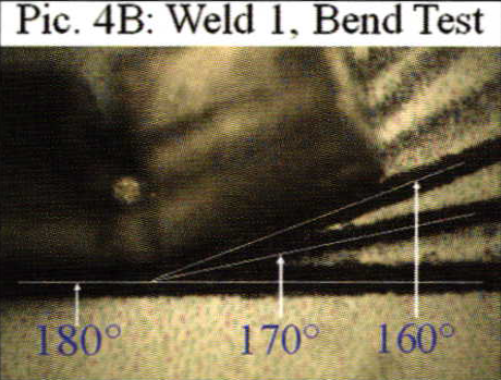 | 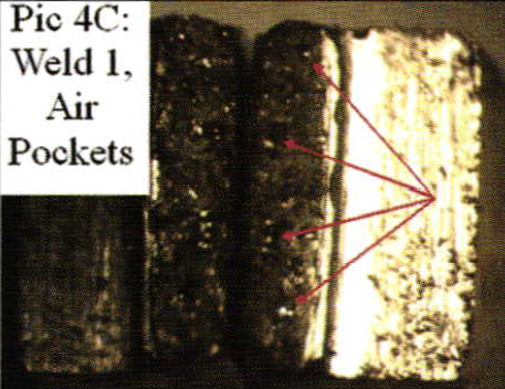 |
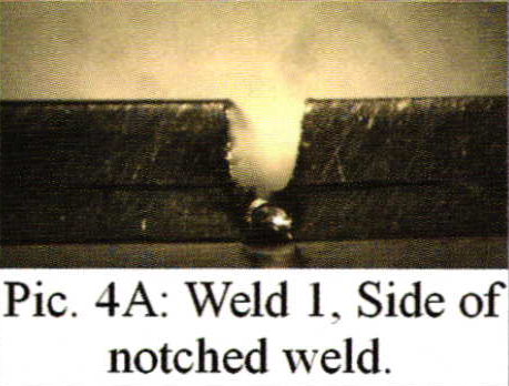
If contact was made, re-notching would be necessary again to relieve compression stress while bending further. Human sensitivity was used to feel and see when the weld started to crack. After the beginning of a crack was determined, the bend angle was measured and documented in Picture 4-B at 160o. A view of the broken weld from the inside, as seen in Picture 4-B, shows evidence of very small air pockets that are very difficult to avoid when holding the piece by hand when welding. Well-balanced energy for proper penetration and melting; consistent, even movement of the piece, and good ability to stay in focus, will reduce these air pockets to a minimum.
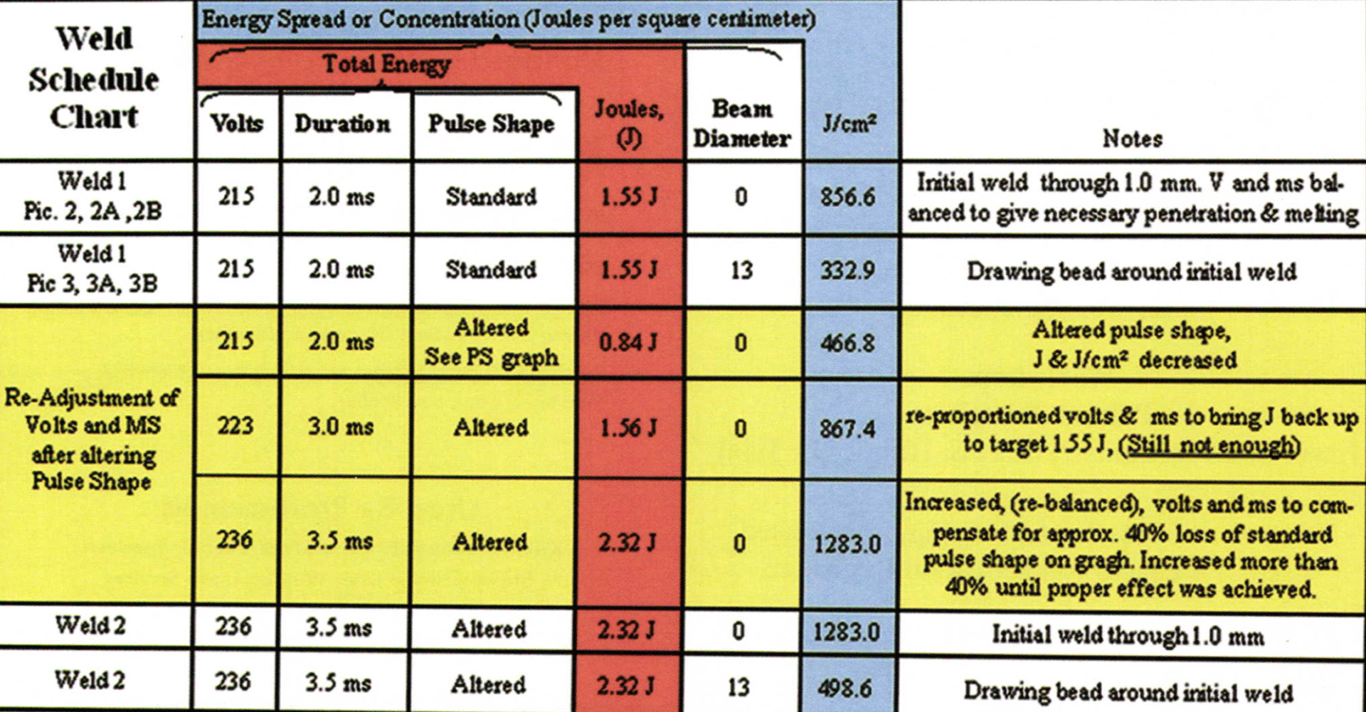
The results of this article's test that are illustrated and discussed here are not as important as the following process for re-adjusting the energy (volts and MS) after the PS has been altered, in any way, from standard. If the particular make and model of machine being used offers: 1.) An energy readout, (Joules), as well as: 2.) An energy spread / concentration readout (J/cm2), then: those displayed readings can be used as references when comparing one pulse shape to another, as well as comparing the visual effect of one weld to another with an altered pulse shape. Equally as important, having those references allows us to re-adjust our energy, after altering the PS. As shown on the yellow highlighted portion of this projects Weld Schedule Chart, altering the pulse from standard reduced J and J/cm2. Weld I initial parameters, (with a standard PS), dictated that we use 1.55 J and 856.6 J/cm2 for the initial weld of the 1mm thick stock in Pic. 2. After altering the PS the energy can be brought back up to 1.55 J by increasing volts, MS, or more likely, a combination of both, in order to achieve the required penetration and melting with the altered PS.
Simply increasing the J, and or J/cm2to the targeted reference (in this case 1.55J / 856.6 J/cm2) will not always produce adequate penetration and melting into the same 1 mm piece. Of course volts and MShave to be balanced for the chosen beam diameter, regardless of PS, (See Article: "Proportions and Effects"). However, even if the target 1 55 J and 856.6 J/cm2 is selected after altering the pulse, the penetration and melting effects are often less than was achieved with the standard pulse shape. Therefore a given J and J/cm2 will produce one effect in a particular PS and a different effect in another PS. (See article: "More About Pulse Shaping"). When comparing the effects of a given J and J/cm2in standard PS, to an altered PS, the effect will always be less aggressive in the altered PS.
The difference in effect is related to the percentage of change that was made from the standard to the altered. The blue line, in Weld 2 PS Graph, indicates the altered pulse shape used. The red line is included to show the difference between Weld I PS graph and Weld 2 PS graph. The difference is estimated visually basedupon the percentage of decrease from the standard PS and is shown as the gray area on Weld 2 PS graph. More drastic reductions in area on the graph, require more drastic increases in volts and MS to get the penetration and melting necessary, even if that means going over the 40% difference (as shown in Weld 2 PS Graph). Here it was necessary to go over the 1.55 J and 856.6 J/cm2. The energy was increased by increasing (balancing) volts and MS until adequate penetration and melting was achieved, and no further. If that means going over the target J and J/cm2, then so be it. It is more important to achieve the correct penetration and melting, than get too caught up in all these numbers.
The altered PS in Weld 2 PS Graph was chosen based on curiosity. We were curious if a slightly slower pulse heat time, and much slower pulse cool time, would produce more ductility in the weld in a similar way to the slower cooling time that Ni WG requires when annealing with a torch at the bench. After altering the pulse and re-adjusting the energy, the same welding and failure test process was used as in Weld 1.
The small notch that is illustrated in Picture 4 had to be re-cut during the bending of Weld 2, because the walls of the notch were contacting before the rest of the weld failed. The smaller notch on Weld 2 had to be re-notched once because during bending the walls of the notch contacted before ripping or cracking in the rest of the weld.
There are many variables present when conducting this kind of testing. For example, if any one of the pulse shape reference points were to be moved over the X or Y axis in even the slightest amount, then in order to really know if the altered pulse shape was producing more ductile results, a new test similar to this one would have to be performed. If any part of the alloy content were changed (even the slightest percentage), then a new set of tests would be necessary (with various sets of custom altered pulse shapes, as well as tempers, if heat treatable). The temper of the piece is also a variable. A medium temper was chosen for this test. We have conducted similar testing on l4k WG that was extremely work hardened. Video of the work hardened piece is included in this project's more comprehensive report. Parameters are variables; the primary purpose of this report was to show one method of taking steps to isolate the variables, mainly related to the adjustment of the parameters.
Related Articles:
Pulse Shaping: Energy Over Time
Pulse Shaping: Variable Constants
Nickel White Gold Welding
Related Articles
Laser Welding Sterling Silver

Jewelry Designs: Hope Pendant

950 Palladium: Custom Made Components

Laser Platinum Fabrication


The All-In-One Jewelry Making Solution At Your Fingertips
When you join the Ganoksin community, you get the tools you need to take your work to the next level.
