
Pulse Shaping: Energy Over Time
10 Minute Read
Laser technology is still so new to our industry and there is still so much to discover. Fortunately, I believe that as jewelers, we are the ones left to do a lot of the discovering. My only intention with this article is to give the reader an overview of what Pulse Shaping is, its history, and to provoke some food for thought in the way that we, as jewelers, are all discovering new techniques with laser welding technology.
The methods I discuss of using it, within our industry, are based first on my own trial and error, and secondly on the little bit of knowledge I have been able to gain from more knowledgeable people who use it within other industries.
In our industry, Pulse Shaping is some what of an on going experiment because it has yet to be truly rested on our applications. For that matter our applications are so much more diverse than any industry I have seen using laser welding, that I can well imagine Pulse Shaping will find its uses for any jeweler that is willing to explore the many variables it has to offer. If readers of this article are using Pulse Shaping in any way, I would be interested in hearing from you. I can be reached at 619-239-5842 or lasers@mantech.info.
Pulse Shaping is having the ability to control the amount of laser energy distribution over the laser pulse duration, or energy distribution over time. The method of pulse shaping that I am familiar with, in the Rofin that I use, was developed and is patented by a German company named Baasel Laser Tech., (BLT). BLT was able to develop Pulse Shaping in the fashion that they did because of large amounts of research and development that they put into their power supplies. This was prompted by industries wanting the variables that Pulse Shaping offered. BLT is also in the power supply business and heavily invested in producing their own power supplies as well as power supplies for other makes of industrial lasers. BLT was purchased by another German industrial laser firm, known as Rofin-Sinar. BLT is now known as Rofin-Baasel.
Pulse Shaping and Laser Welding Technology, like a lot of other technology, was not originally intended for the jewelry industry. The micro-welding that we are using for jewelry has its roots in medical device manufacturing and electronics, as well as scientific research and development among other industries as well. Many of these other industries have very demanding standards and are willing to pay for research in the development of their product. In the case of laser welding, cutting, and marking of devices that are intended for permanent placement within the human body (such as orthopedic devices, artery stints, electronic connections for pulmonary assistance systems) metallurgical results must undergo strict testing for highest possible quality.
The principles behind Pulse Shaping, in Laser Welding, go hand in hand with the principles of heat treating and annealing. By controlling the rate at which a particular material is heated or cooled, the grain structure within the weld can be manipulated to achieve various desired metallurgical properties, such as hardness, strength, ductility, toughness, malleability thermal expansion, conductivity and elongation. The achievement of these various properties, within a laser weld, using pulse shaping in any given material, depends on many variables and requires extensive testing that can be time consuming and costly.
As far as the jewelry industry is concerned, true metallurgical testing has not been accomplished on the noble metals and alloys we are working with to determine the optimum pulse shapes to achieve various physical properties within the weld. There are many people out there who will swear by certain shapes, myself included, but testing to Prove optimum shapes is expensive. The jewelry industry does not offer great returns on this type of research. With technology like this I am afraid that jewelers are left to become something like mad scientists. However, isn't that usually the case with more of the tools and machines that find their way into our jewelry shops?
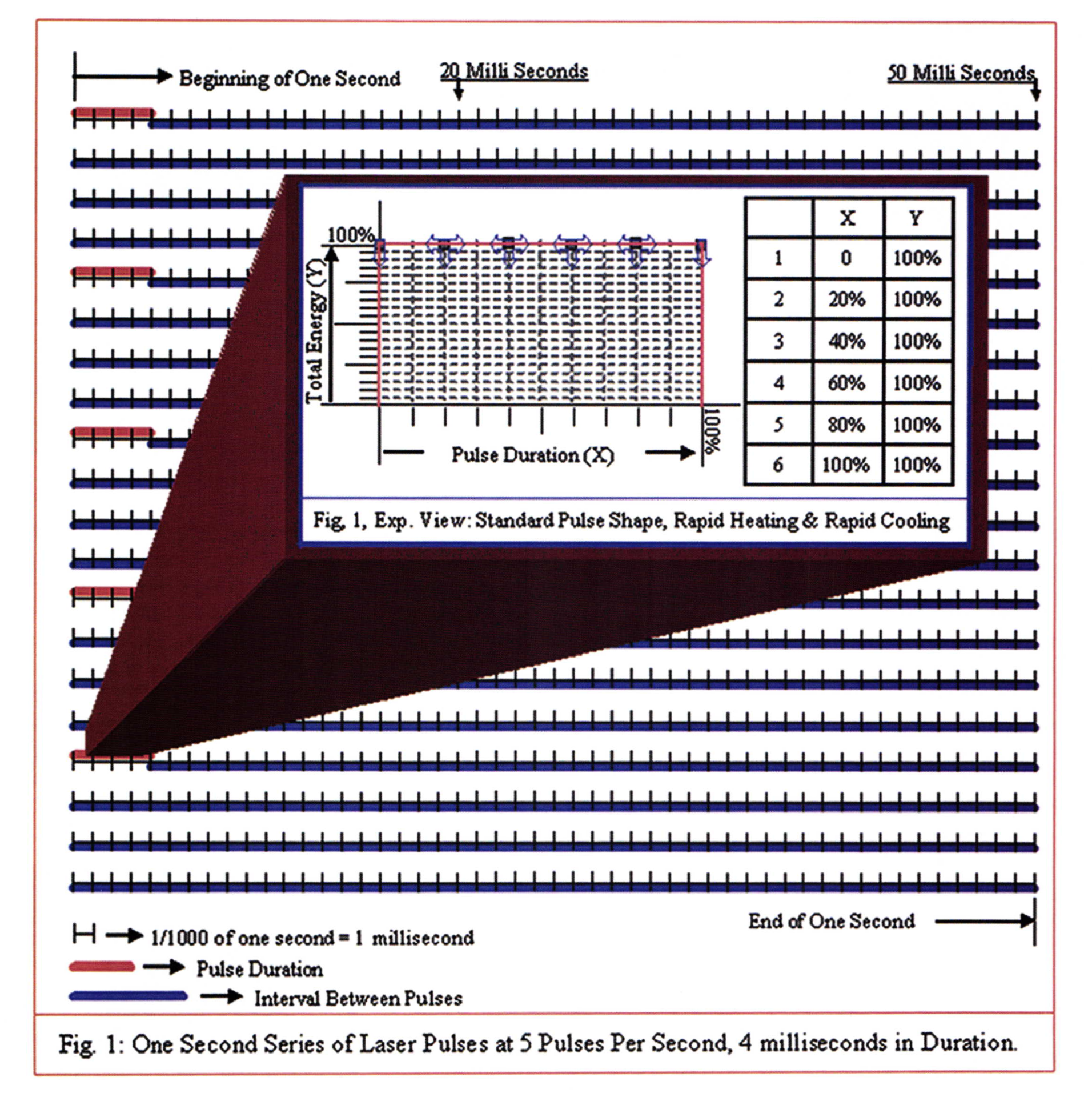
As you may recall from prior articles within this series, total energy is determined by a combination of Volts and Pulse Duration. These are both adjustable parameters. Total energy for pulse shaping purposes is expressed as a Percentage on the Y axis of a graph, as shown in the expanded view of a standard pulse shape in figure 1. In the expanded view of figure 1, on the Y axis of the graph, the energy within the laser pulse is going from 0 to 100% of whatever energy was selected by the operator through Volts and Duration.
It is valuable to have an energy meter built into the machine's display, so that the operator knows the exact amount of energy that is chosen. The standard pulse shape shown in figure 1 delivers 100% of the selected energy to the weld joint immediately upon actuating a laser pulse. 100% of the selected energy (in figure 1) stays exposed to the weld joint for a period of time that is also determined by the operator through Pulse Duration, and is expressed as a percentage, on the X axis of figure 1's expanded view.
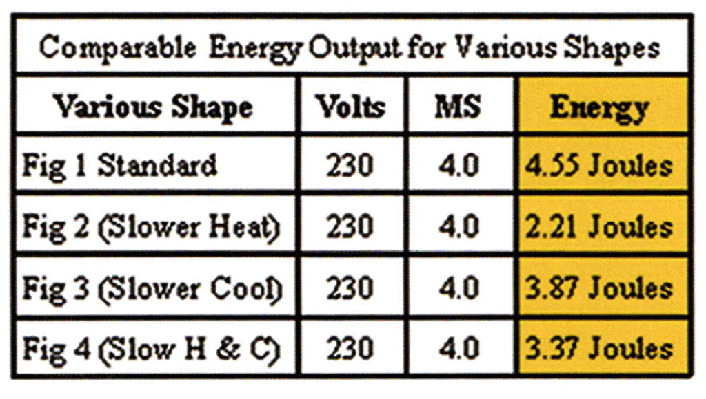
The standard pulse shape in figure 1's expanded view, accomplishes relatively rapid heating and rapid cooling to the weld spot because 100% of the selected energy stays consistent from the immediate beginning of the pulse until it immediately drops to 0 at the end of the pulse. Figure I is what I refer to as the default pulse shape, and is the shape that delivers the maximum amount of energy, as seen in the attached Comparable Energy Output Table that I prepared to compare energy output between all the pulse shapes that we will be looking at.
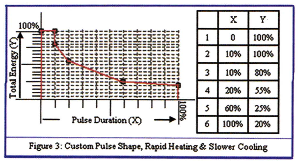
Figure 1 shows one full second divided into 1000 parts, with 5 laser pulses being delivered at a duration of 4 milliseconds, (4/1000ths.), each. The expanded view of figure 1 breaks the 4 millisecond pulses down into fractional amounts of time within the individual pulse, and is illustrated by the reference points with arrows. The arrows indicate that these reference points can be moved over the X axis, as well as the Y axis, to create a customized shape on the graph that will determine a percentage of the selected energy to be delivered within fractional amounts of the selected total pulse duration. When we start dividing the time of one second into such small increments as 1/ l000ths, as well as dividing single pulses into fractions of the total duration, it can seem like things are being put on a pretty small scale. Due to the incredible short increments of time that we are looking at here, there are a couple important features within the machine that should be available for pulse shaping to have a greater range of effectiveness. One must have the ability to either repeat the pulses at a fast rare, such as the 0-20 pulses per second or one must have a wide range of time within the pulse duration to select from, such as the 0.5-50 milliseconds.
Using faster pulse frequencies allows the operator to keep the custom shaped energy exposed within the weld seam. In this case the operator can use lower energies and shorter durations. In this scenario the prior weld spot would nor have a chance to recover, solidify, or freeze, or the recovery time of the prior spot would be limited to some extent, before the next custom shaped pulse comes right in overlapping the prior spot. In this case it becomes more of a consistent customized energy shape that is delivered to the total weld seam rather than a single spot weld.
Also, in the case of faster pulse frequencies, it becomes a balancing act between the particular customized shape of energy and the selected pulse frequency. This balancing act is one more variable thatmust be tested to determine the physical properties that are desired within the metallurgy of the piece being joined. Remember that the original purpose of pulse shaping is to effect the metallurgical properties through the rate of heating and cooling that can be controlled through the delivery ofcustom shaped energy, and in this case, at given pulse frequencies.
Slower pulse frequencies, or even single pulse modes that allow the previous spot to fully recover, usually require longer pulse durations to have much of an effect through pulse shaping. When you see the illustration in fig. 1, of one second divided into 1/ 1000ths, hopefully you get an idea of just how short a duration of 1-20ms is, for example, and even how much shorter the fractional adjustments within the pulse shaping graph are.
This illustrates why longer durations are generally necessary to have a metallurgical effect through pulse shaping. Using longer pulse durations results in higher energy pulses and requires the operator to use slower pulse frequencies (or even deliver single pulses at a time) but still have greater control of heating and cooling rates through custom shaping of the energy. When slower pulse frequencies or a single pulse mode is used an energy meter is necessary because by referencing how much energy was required to gain adequate penetration and melting with a standard shaped pulse, the operator can then customize the pulse shape and use the energy value from the previous standard shaped pulse, as a fixed reference in proportioning the Volts and Duration, (Energy Settings), within the custom shaped pulse. Without having the ability to compare energy output between the various pulse shapes leaves no fixed reference to use when researching the desired effect within the weld.
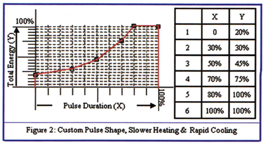
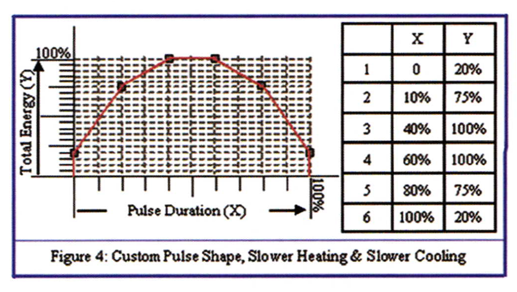
When comparing Figures 1, 2, 3, and 4's pulse shape at given volts and duration, you will notice in the attached Comparable Energy Output Chart that shaping the pulse reduces the total energy output. Figure 1, exp. View, is the standard pulse shape that will always deliver the maximum total energy. If the total energy of figure I was proportioned for adequate penetration and melting, but resulted in undesirable metallurgical properties within the weld, the shape can be customized in innumerable ways to control heating, cooling or both. Customizing the shape will reduce energy output, so the energy settings (Volts & Duration) can be re-proportioned after shaping to bring the energy back up to a level that will give adequate penetration and melting.
Therefore, when customizing the pulse shapes in this fashion, it is necessary to reference the initial energy output used with the initial pulse shape (usually the standard shape) and use that value as a loose point of reference during the trial and error period of finding the correct proportion of energy through Volts and Duration after customizing the shape. It is also necessary to have a large range of pulse duration available in order to have much of an effect between the fractional, and adjustable, points of time (X axis) within the pulse. Using pulse shaping in this way initially reduces the total energy (during trial and error) on the graph, but will require the energy to be brought back up and re-proportioned for the proper penetration and melting. Based on my own experience I have found that I prefer to bring the energy back up, after shaping, by primarily increasing duration. I will bring the volts up to some extent, but I have been primarily playing with bringing up duration. I will re-proportion the energy after shaping until it is getting the correct results of penetration and melting (as I have discussed in my last article).
Proportioning the energy in this way will bring the total energy back up to the same, or sometimes even higher, than with the original shaped pulse. The only variation is that the energy is being distributed differently over the total time of the pulse, in that the heating rate, cooling rate, or both are manipulated. Or as in the case of faster frequencies and shorter durations, the energy is being manipulated over the total sequential time of the laser being exposed to the entire weld seam through many pulses at higher pulse frequencies.
One application that I am most curious about, and currently testing the effects of Pulse Shaping is in the welding of Nickel White Gold, (Ni WG). Ni WG has a tendency to become brittle and porous when welding with higher energy than is required to weld through a relatively thicker piece, such as the 2.5 mm, or thicker, ring shank that I discussed in my last article, regarding the effects of proportioning energy Parameters when weldinga2.5mm thick 18k YG ring shank. For that reason, there are various techniques that are extremely helpful. These techniques include but are not limited to Pulse Shaping. I plan on writing about techniques of welding of Ni WG in my next article. In doing so, I will add my thoughts on Pulse Shaping as it applies to that application. Until then I wish you happy and prosperous welding.
Related Article:
Pulse Shaping: Variable Constants
Nickel White Gold Welding
Pulse Shaping Test, 14k Ni WG
Related Articles
Benchtop Hydroflux Welders

Jewelry Designs: Hope Pendant

Repairing an Omega Earring Clip

Step-by-Step Guide to Upsizing Rings


The All-In-One Jewelry Making Solution At Your Fingertips
When you join the Ganoksin community, you get the tools you need to take your work to the next level.
