
CAD/CAM Techniques
6 Minute Read
The strength of Computer Aided Design & Manufacturing is similar to that of any other tool on the bench:it is most effective when itis the right tool for the job.Gemvision's Matrix 4.0 provides users with powerful design, presentation,and production capabilities.
However, it will sometimes be easier or more desirable to complete certain aspects of a piece by hand rather than on-screen. When this is the case, it is important not to overlook the impact of digital presentation, both for you the designer and for your customer.
Production and Presentation
Design elements such as fine mill grain, finished prongs,and subtly-textured metals are elements that, in somecases, can only be added in post-production. Though they will necessarily be left out of the production model or theversion that will be milled or prototype, it will often be desirable to place them in a "presentation" version of the model or the one that your customer will see.
Each of these design elements can be created for the presentation model in just a few minutes time using simple steps that even a beginning Matrix user can perform. Whether the goal of the presentation model is to inspire you, as the designer, with a more complete view of the finished piece while you work, or to present a lifelike rendering to your customer for approval, each of the techniques described below will give both the digital model and the rendering a look that more closely resembles the finished piece.
Adding Millgrain
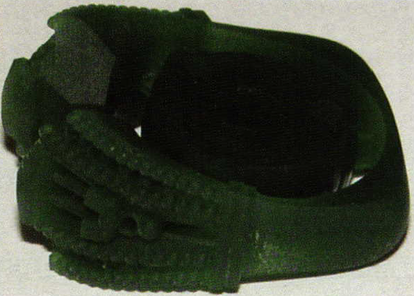
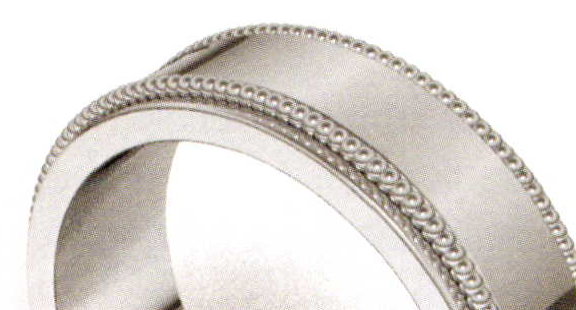
In the case of millgrain, the first step is to determine whether CAD/CAM is best used to produce or just to present the design. Beads with a minimum diameter of 0.6 mm can be successfully produced on Gemvision's Revo mill, as shown in the wax below.
If finer millgrain is called for in the design, it is best to add it by hand. It then takes only minutes, even with basic Matrix skills, to add this effect to a presentation model for the rendering.
- To begin, save a copy of the production model or the version without the millgrain. Then, use the appropriate curve tool to draw a curve along which to place the millgrain. On a single surface, use Extract I so curve to create a curve that follows the shape of the surface, or draw a curve in space and use Project to place the curve onto the surface.
When the millgrain will follow an edge, as in the illustration below, use the Dup Edge command also found in the Curve fly-out menu. Select the edge or edges on which to place acurve and then join the curves together if more than one edge was selected.
- Next, use the Sphere tool found in the Solid fly-out menu to create a sphere about the same size as the millgrain you will be adding by hand in post-production. Select the sphere in space and "click and drag" the mouse to position the sphere at the end of the curve that was placed in the first step, making sure that it is sunk into the surface the appropriate amount.
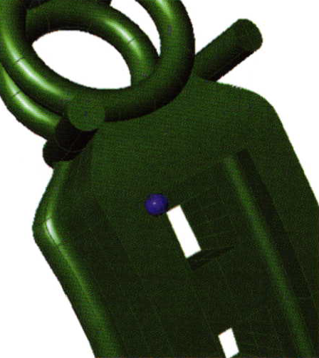
- Click on the Array Along Curve command, which is found in the Transform fly-out menu, and indicate a distance between the spheres to be arrayed along the path curve that was created in step 1. Sometimes, finding the correct distance will take a little bit of trial and error. In this case, spheres 0.4 mm in diameter were placed 0.3 mm apart. Then, Mirror the beads four times to create millgrain all around the model. In the illustration below, compare the model created for presentation (left) to the one created for production (right).

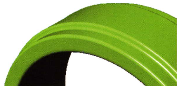
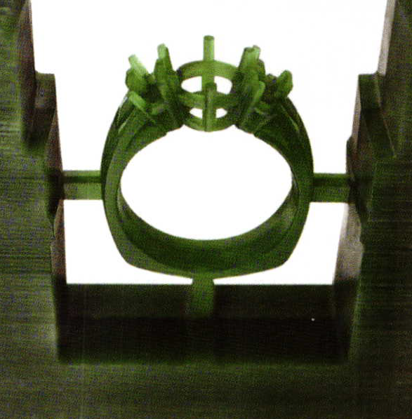
One final note: when the millgrain will be added during post-production, it may be useful to model an additional metal "ridge" on the production model in preparation for using the millgrain tool, as shown in the model below. This ridge was created at the profile level by drawing the desired cross-section curve for the ring inside the Edit Profile tool found in Profile Placer. (The millgrain added for the presentation model was created using the method described above.)
Finishing Prongs
Because Matrix can cut gem seats to the exact depth of the stones, it is often best to prepare the gem layout in the software. However, it may be more desirable to add prongs or beads on the bench.
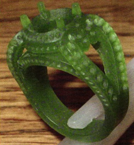
Seats milled to proper depth for gems; prongs to be added Post-Production (Image courtesy of Matt Feliksa, Golden Sun Manufacturing)
At other times, the user is best serviced by producing prongs in the software using Head Builder or Prong Placer. Both builders can create prongs with additional length in preparation for finishing after the model is cast.
Adding length to the prongs in the production model does not contribute to a "finished" look for the model. Depending on need, there are a few different methods that can be used in Matrix to create the look of finished prongs for a presentation model.
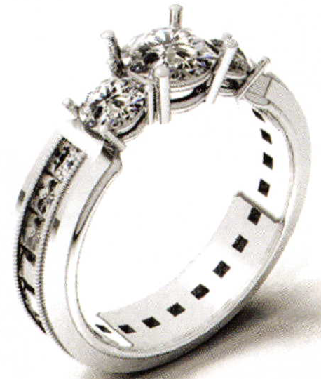
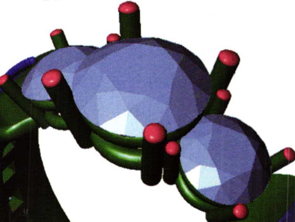
- For prongs created in Head Builder, start with the Extract Surface command and extract the flat top from each of the prongs. Delete the extracted surfaces. Next, use the Split Edge command found in the Utilities menu and split the open edge at the top ofthe Prong at its midpoint. Use the surface command Blend between the two edges to create a nicely-rounded Prong that will appear more realistic - and more appealing - in the rendering.
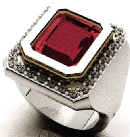
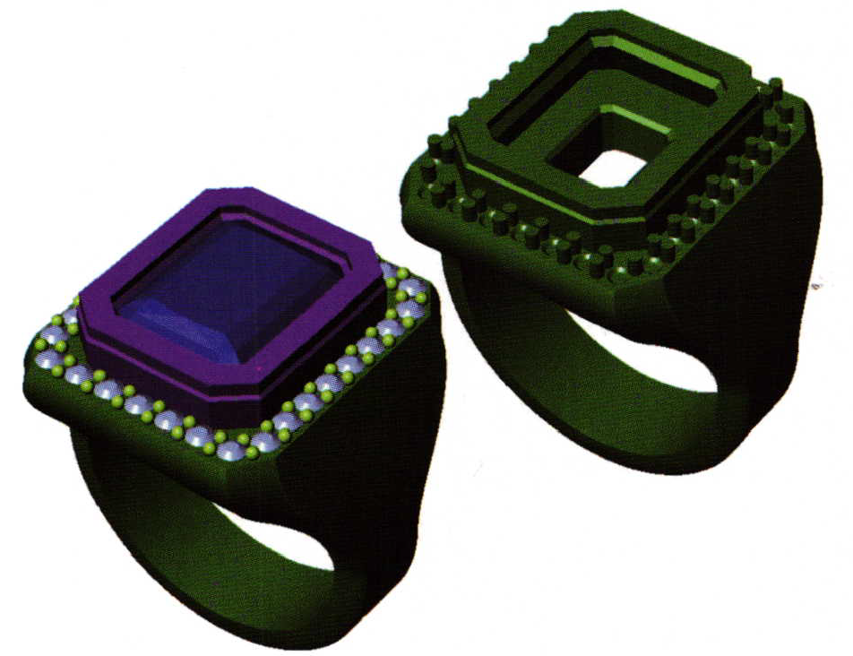
- To add prongs to a gem line in Matrix, use either Prong Placer builder, which places a row of prongs automatically, or the Gem on Surface tool, which places prongs one-by-one. In both cases, the option to draw the prong as a bead is provided within the interface. Select this option and place beads for the presentation model. Then, Job Bag the results and use this model later on for rendering. To create the production model, Undo the beads, and then switch the option in the builder interface from "Beads" to "Prongs". Create prongs of the desired length and orientation. If necessary, Boolean Union the prongs to the model. Compare the models for presentation (left) and production (right) below:
Creating a Textured Finish
Currently, the best way to prepare a model with subtle texture, such as a Florentine, bead blast, or stone finish, is on the bench, not with a mill. However, Render Builder in Matrix provides an effective way to show your customer how a finished piece will look in a textured metal. To add texture to one part of a rendered model and leave the rest smooth.it is important to create the part (or parts) as separate surfaces. That way, the textured metal can be applied to one surface in Render Builder and the smooth metal can be applied to the remainder of the model. Depending on the type of model you are creating (a polysurface or a single surface, such as a band); there are two ways to do this:
- For a polysurface, this is easy to do using the Extract Surface command explained earlier. Extract the surface and place it on a different layer color. In Render Builder, apply the textured material to the extracted surface and the smooth material to the remainder of the model.
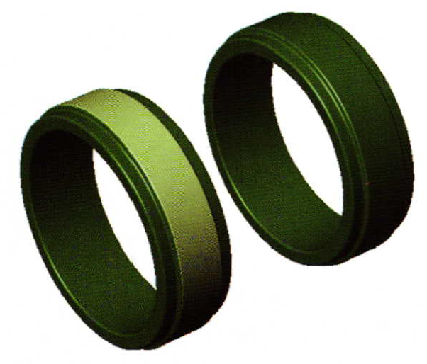
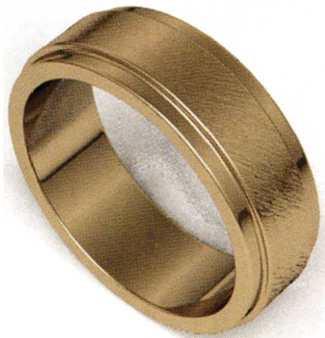
- For a single surface, such as a band, use Extract Isocurve to place a curve on the surface of the band that splits it the desired distance away from one side. Mirror this curve to the other side of the band to create a symmetrical cut. Then, Split the surface of the band with the two curves. Place the split surface on a different layer color. Now, select one surface and apply a textured metal, such as "24KyelIow brushed", to it in Render Builder. Apply a traditional metal to the remainder of the model and render the piece. Again, the models for presentation (left) and production (right) are shown.
Related Articles
Social Networking Tips for Jewelry Companies

The Washington Guild of Goldsmiths

Artists Who Write

The Jewelry of Reiko Ishiyama


The All-In-One Jewelry Making Solution At Your Fingertips
When you join the Ganoksin community, you get the tools you need to take your work to the next level.
