
Beam Path Check
5 Minute Read
With the Nd:Yag Micro Laser Welders, being used by the jewelry, and other industrial manufacturing / repair industries, there is a very simple test that can provide a lot of information regarding the integrity of the laser beam. In the world of laser technology, engineering, and physics this test is called a Mode Burn. I simply like to refer to it as a Beam Path Check or BPC for short.
I refer to it as beam path check, (BPC), because it does much to test the integrity of all lenses, mirrors, as well as the YAG rod, within the path of the beam as the laser beam is generated, delivered, and focused to the welding point. The BPC is an extremely useful test for potential problems that can occur to all components within the laser beams path.
However, this article will primarily discuss using the BPC to determine normal wear that occurs to the protecting lens. The protecting lens is a consumable part that will naturally take wear during welding. This article does not recommend that any other parts within the beam path be further tested, adjusted, or replaced unless under guidance from a technical representative of the machine's manufacturer.
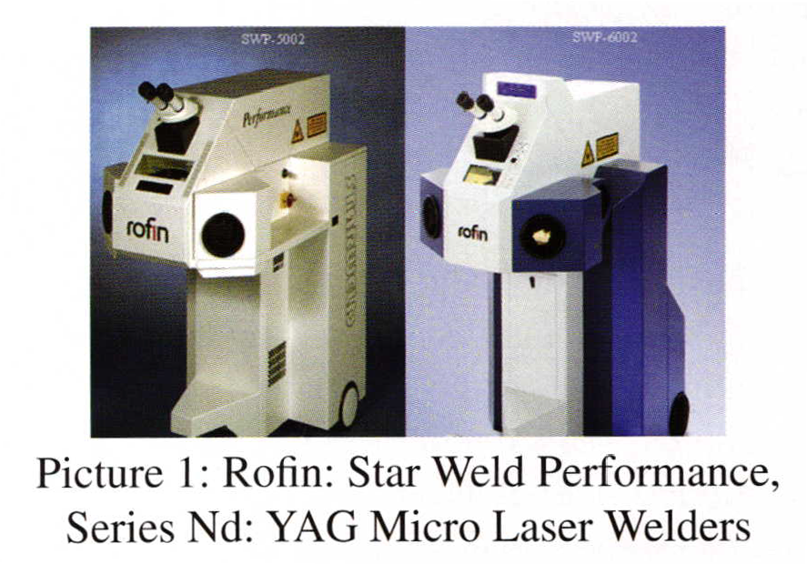
The procedure outlined here will be in reference to two models of machines that are currently widely used in many micro laser welding applications of many industries. These two machines are manufactured by Rofin-Baasel and are the Starweld Performance, Models: 5002 and 6002. (As Pictured). The BPC procedures will likely be very similar for other makes and models of Nd:YAG laser welders, but should be checked with the specific manufacturer.
Performing a BPC is quite simple. A piece of special paper is required. It is commonly referred to as spot paper because the BPC burns a laser spot onto the paper. Spot paper is a heavy weight, white paper, which is coated on one side with ablack film. At first glance, one would think that it is a glossy black paper. However, the black is a coating that will burn off of the paper, showing a white paper spot where it is exposed to the laser. The spot paper can be acquired from the manufacturer of the machine.
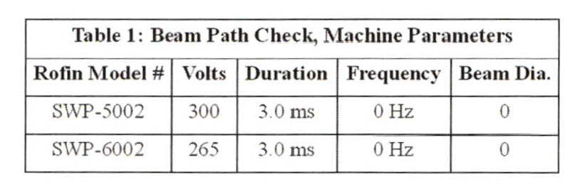
Machines that are used heavily, and where the work is being held by hand, (as is the case in the majority of jewelry industry applications), a laser mark usually gets burned into the machine's working compartment floor, at point F in Illustration 1. The spot paper is held flat on the compartment floor, with the black coated portion of the spot paper facing up, and covering the laser mark on the floor, (Illustration 1). A laser pulse, at parameters specified in Table 1 is then released onto the Paper.
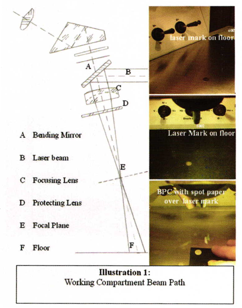
A laser mark can be made onto the floor by going to the specified parameters in Table I and hitting the floor of the compartment multiple times with the laser. The mark on the compartment floor will give the operator a constant reference as to where the beam path is.
The laser mark allows the operator to easily place an unused portion of the spot paper within the beam path for accomplishing the BPC.
The burned away black coating on the spot paper tells the story of the BPC. The best results of the BPC are when the white spot is perfectly round without un_ burned black areas within the white spot, on the paper. Obstructions anywhere within the laser beam path will cast a shadow in the laser beam and show up, in the exact shape of the obstruction, within the white spot on the paper.
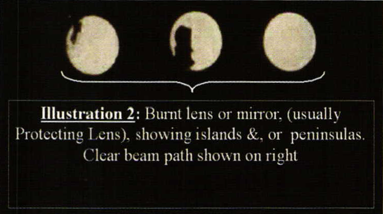
The most common cause of obstructions in the beam path are burn spots on the protecting lens. Illustration 2 shows some examples of odd shaped un-burned islands and/or peninsulas on the spot paper. In the case of a burned protecting lens, (on Rofin machines and possibly on others), the operator can reach in and turn the protecting lens by hand. Since the laser beam travels through the protecting lens off center, the burn spot on the lens is turned out of the beam path. This feature prolongs the usefulness of the lens. Another quick BPC will determine if the beam is un-obstructed through the lens.
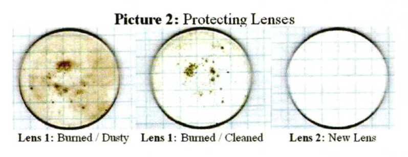
Picture 2 is of protecting lenses that were scanned with a graph paper background for better viewing contrast. The lens on the left has burn spots and is coated with a dusty film. The dusty film accumulates from welding fumes. The dust accumulation on the lens is reduced by keeping the machines work compartment evacuation system calibrated and maintained properly, (periodic evacuation fan calibration, and HEPA air filter replacement as per manufacturer's maintenance manual). (Of course the evacuation system is also important to maintain, in order to insure a healthy work environment). It is also recommended that the protecting lens be cleaned often, (once per day for heavy use). Even small amounts of dust build up on the protecting lens will eventually be burned into the lens in the path of the beam.
The longer the dust is left on the lens, the shorter the life of the lens will be, especially when working at high energy welding parameters. Removing and cleaning the lens is a very simple task. The purpose of the protecting lens is to protect the much more expensive, focusing lens, from getting burned. Eventually there will no longer be any clear areas in the protecting lens for the beam to travel through. This is easily determined by performing a series of BPCs while rotating the lens between checks.
The BPC tells much regarding all other parts within the beam path. This article will not go into that amount of detail. An operator who understands how to perform the BPC will be able to work easier with technical support representatives in the case that the condition of other parts within the beam path may need to be determined. Keeping a strip of spotpaperclose by the machine, and programming the BPC parameters into one of the machines memory cells for a quick BPC is often very useful. The BPC is very useful when performing a very delicate welding job, and one wishes to insure that the full amount of selected energy is actually making it to the weld spot.
Related Articles

Jewelers Saws Tested: A Hands-On Review Of The Knew Concepts Precision Lineup

Bench Mag Favorite Tips 2002

Fabricating a Free Form Opal Pendant
Kiln Questions


The All-In-One Jewelry Making Solution At Your Fingertips
When you join the Ganoksin community, you get the tools you need to take your work to the next level.
