
Welding Aluminum for Successful Anodizing
14 Minute Read
This article includes descriptions of dangerous activities. These descriptions are not to be deemed instruction, any inference to the contrary being hereby specifically denied.
Aluminum has been researched since the late eighteenth century, when the French chemist Antoine Lavoisier theorized that the metal which had been known as "alumine" was actually on oxide of a metal with a shang affinity for oxygen. Aluminum are was first discovered at Les Baux, France, and was therefore named bauxite. In 1854 a Frenchman named Henri Sainte Claire Deville developed a chemical means to extract aluminum from ore to obtain a pure metal. Because of its rarity, refined aluminum was more precious than gold and was exhibited at the Paris Exhibition of 1855 next to the British Crown Jewels. It was not until 1886 that the American Charles Martin Hall, studying at Oberlin College in Ohio, made it possible to produce aluminum efficiently, using on electrolytic process. Eventually the material would be exploited by industry in automobiles, aircraft, utensils and electrical equipment.
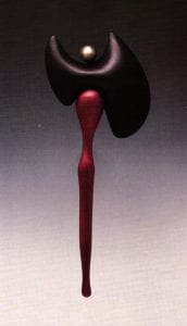
Aluminum has been used in jewelry and metalsmithing because of its light weight and capacity for coloration through anodizing. Artists have exploited the material's properties in exciting, colorful, innovative works for many years through methods of cold joining. Hot joining methods, however, have not been employed to any extent.
My work began in 1989, with the support of a SNAG research grant. I proposed to develop a means to weld aluminum for successful anodizing, to create an object whose seams would not appear during the anodizing process, and to do so in an affordable package. My experience with pewter fabrication helped me to approach aluminum in an unconventional way. Pewter allows the fabrication of objects through fusing, which results in a visually seamless form that is free from any signs of the fabrication process. This type of fabrication served as the model for my research. In theory, the use of an aluminum filler material of on alloy similar to that of the component parts would create on invisible weld and provide consistent color anodizing. Tungsten inert gas (TIG) welding hos proven effective for high-quality welds but requires equipment that is often too expensive for the individual and many institutions. Aluminum solders contain so many other metals that color matching the seam and base metal before or after anodizing is impossible.
The difficulties in welding aluminum have always been the tenacious oxide layer and aluminum's propensity to conduct heat. Successful welding would require freeing the aluminum of the oxide skin, reaching the weld temperature locally, and welding without the reintroduction of oxygen.
Welding Aluminum
The first of three methods that I applied, flameless torch inert gas welding, was unsuccessful but provided valuable insight into the problems that had always made aluminum welding difficult. The flameless torch is a ferrous alloy filament shielded in a quartz tube. A variable electric power supply is used to heat the filament, which then superheats the flow of inert gas through the tube to temperatures in excess of 2000° F (1100°C). The flameless torch, which was provided by GTE/Sylvania, appeared to be both affordable and applicable to the technology and method I proposed. A second model of the torch, with a fused alumina shield, a smaller focused orifice and a tungsten filament, was also provided. It is capable of temperatures of 1800° F (1000° C) at the tip, but temperatures drop off very quickly with any distance from the orifice. A dial controller provides variable power to coincide with the volume of the gas flow. A safety switch is used to isolate and ground the operation.
I built a work space from a salvaged galvanized steel box to create on oxygen-free, inert environment. Slitted rubber armholes allowed freedom of movement without the re-entrance of oxygen. The viewing window from a stove door was salvaged to provide safe, inexpensive, heat-resistant glass. The flow of nitrogen from the flameless torch would displace any available oxygen, venting it out the small chimney of the box. This created a positive inert atmosphere in which the aluminum and filler material could be cleaned both chemically with caustic soda and mechanically with abrasives. In theory, there would be no opportunity for oxidation to recur. Once skipped, the aluminum would melt locally and flow freely together, like pewter.
Unfortunately, my theory did not hold up in practice. Although the environment was oxygen-free to the point of putting out a candle, the aluminum still acquired an oxide layer, on both the filler and the components. Furthermore, because aluminum has such a great capacity for dispersing heat, it took full power with a forceful gas stream to reach the welding temperature. When it did melt, it was not localized enough to be acceptable. The blast of superheated nitrogen tended to tear and blow away the molten material, making joining impossible. Fluxes were considered as a means to degrade the oxide layer, but heat dispersion would remain a problem. With a gas stream of 1700° F (900° C), a great deal of heat radiated away from the tool, which mode extended periods of welding in the closed environment very uncomfortable for the hands.
This portion of my research illustrated the two major hindrances in joining aluminum: omnipresent oxidation and heat dispersion. At this point I realized that it was not necessary for me to be an inventor. Rather, I could turn to existing technology with added consideration for the anodizing process. Aluminum welding technology dates from early in this century. Torch welding became more and more refined, only to be overshadowed by heli-arc welding. Oxy-fuel torch welding provided X-ray quality welds for the aircraft industry during World War ll. A welder whose grandfather had been trained in torch welding quickly brought me up to speed. Reviving this technology would make the process affordable to almost anyone working in the field. It turned out to be the most successful and reliable welding method of the three that I attempted.
Welding aluminum for successful anodizing could be assured through attention to four essential considerations:
- Aluminum alloy and corresponding filler material alloy
- Cleaners and fluxes
- Flame adjustment and welding procedure
- Precleaning process for anodizing
The selection of the alloy used for the fabrication was the most important factor. Aluminum alloys are designated by a four-digit number, with each new first digit being called a series, as in 1000 series, 2000 series, up through 8000 series. The aluminum alloy and temper designation system is nationally registered and universal throughout industry. Alloy number 1100, a "commercial pure" aluminum, was most consistent for quality color-matched welds. The 1100 alloy also provided the most brilliant colors. Alloy number 3003 also yielded good results. Number 6061 is a magnesium-silicon alloy that combines machinability with good color quality in anodizing.
Wrought aluminum sheet is frequently labeled with a gauge number, alloy number and temper designation. For torch welding, 18-, 16- and 14-gauge sheet were most appropriate. Twenty-gauge and above were possible but unnecessary because the material's weight was not often a factor. Eighteen-gauge and below provided adequate thickness to prevent slumping and allowed a less accelerated welding travel speed. The temper designation did not appear to be a significant factor in coloring. It did, however, need to be considered for the fabrication method. A moderate to hard designation would be appropriate for direct sheet fabrication, for durability and for resilience. Dead soft aluminum would be ideal for spinning, die forming, raising and forging.
After the alloy was selected, a filler material designated for color match had to be chosen. A publication by the Aluminum Association entitled Welding Aluminum was an endless source of technical information and suggestions. It provided the essentials on alloys and their characteristics, joining methods, filler materials, preparations for joining, all types of welding, safe practices and supplementary readings. I tested a number of filler materials. My experience in fusing pewter led me to believe that the ideal filler would be a portion of the parent metal itself. A long ship of the original material would provide a filler rod identically matched with the alloy of the components. I had better results, however, with commercial filler rods, which often include about 5% silicon. This lowers the material's viscosity and allows a smoother flowing joint. Filler rod 1100 was suggested for alloys 1100 and 3003. Filler rod 5654 was recommended for alloy 606 l but seemed to be unavailable. Rather than commit to a material so difficult to locate, I substituted the second choice, filler 5356.
The cleaning of the materials was important to the consistency of the seam and the makeup of the bead. Preparing to weld was very similar to silver soldering in that each component and filler rod needed to be thoroughly cleaned. Once the aluminum had been scrubbed to a white scratched finish, it was chemically stripped with a product designed for pre-weld cleaning, which was brushed on, left to stand for 2 minutes, and rinsed under cold water: This combination of mechanical and chemical cleaning assured the greatest reduction of the oxide layer. All materials, components and fillers were put through this cleaning process just prior to welding and then were immediately fluxed.
Early on it became evident that the flux was the most important and most hazardous component in the process. It was a very active participant in the procedure through its ability to degrade the aluminum oxide skin and allow penetration of the filler material. Active or aggressive fluxes are fluoride and chloride based. Sources of these hazardous materials always furnish a material safety data sheet (MSDS). In this case, the hazards include skin, nasal and respiratory irritation; osseous fluorosis; increased radiographic density of the bones; mottling of teeth; neuromuscular effects and other hazardous results. It was imperative that these materials be used with a respirator and the filters designated for these hazards. The fluxes come in powder form and were most effectively applied when mixed with water or alcohol. The milky slurry of flux was applied on and around the joint to provide ample local protection and "activity." The filler rod was also fluxed to degrade the oxide layer and allow a smoother melt.
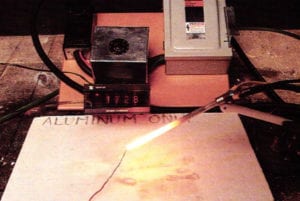
To provide the necessary intense localized heat, an oxyacetylene torch was selected. A full-sized torch was found to be slightly cumbersome, but a mid-sized torch with a 0 or 00 tip provided a full range of flame sizes with great freedom of movement. I also tested the Little Torch, a compact, portable and affordable oxyacetylene system. It was the most maneuverable and easily adjusted torch and represented an affordable means to weld aluminum with great precision.
The adjustment of the torch was the final consideration before welding. A neutral flame was essential to provide enough concentrated heat without the introduction of excess acetylene or oxygen to the weld. The refinement of this flame was important to achieve consistent welds. The torch was adjusted so that the neutral flame developed on inner cone about 3/16 inch long. Eye protection rated for oxyacetylene welding was worn at all times, from the point of lighting and adjusting the torch until it was turned off.
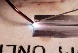
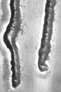
To begin welding, I positioned the inner cone with its tip very nearly touching the seam, about ⅛ inch inside the end or edge of a component. With a flame of appropriate size, the base metal would begin to melt within 3 to 5 seconds. If it took any longer than this, I increased both gas flows to produce a slightly larger neutral flame. When the metal began to melt, I had to push the filler rod into line with the flame with a pecking gesture particular to this type of welding. Holding the torch in my more dexterous hand (unlike for most welding), l directed the flame down the seam at a 45° angle to preheat the path. In the other hand I held the filler rod at a 45° angle mirroring the position of the torch.
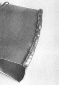
The weld bead was formed by tapping or pecking with the tip of the filler rod in the melt zone, leaving a fillet. The tapping was the final means to break through the thin, weak oxide layer. The material melted and flowed freely, creating a bright metal pool. I quickly developed a sense of the proper travel speed, keeping in mind that the parent metal had to melt before the next tap of the filler rod. With a sense of the travel speed, I was able to form a smooth and consistent bead. It was surprising to note that a 3-foot section of filler rod served to weld a 1-foot section of seam. If for some reason the weld was interrupted, I reheated the termination of the weld to a melt and penetrated with the filler rod. When the seam was completed and had air-cooled, I rinsed the flux off under warm water. There were a number of joints for which this process was effective. The T-joint, the butt joint, the flanged butt joint and the lap-joint were all appropriate where accessible for grinding and finishing afterward.
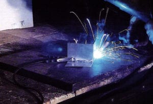
The third means that I tested was metal inert gas (MIG) welding. Small MIG welders were available for about $200, making them viable in my search for affordable technology. They appeared to be toy-like machines that boosted the ability to weld ¼-inch steel, stainless and aluminum on 110-volt, single-phase wall current. The Uno MIG was a great little welder, with a few parts to assemble and a small but useful manual. It was easily assembled and loaded with a 1-pound spool of 5356 filler wire. Most of its functions were self-explanatory and well documented in the manual. A rheostat and four-position switch controlled the wire feed speed and power output respectively. They provided a range of power and feed speeds well suited for welding aluminum. One-pound spools of a variety of filler alloys were easy to obtain, as were replacement tips, a couple of which burned up in the learning process. A second collar was purchased specifically for aluminum to prevent possible contamination when welding other metals. Pure organ was used as the inert shield gas.
A considerable amount of practice was required to develop a sense for forming a quality bead. Practice runs allowed testing of various power settings and wire feed speeds. My initial welds were dirty, lumpy and inconsistent, but practice allowed for improvement. Leather gloves, long sleeves, face and eye protection were alwoys worn in the arc welding operation. The welder performed well, but results did not equal those in torch welding.
In 1990 a research grant from the Lilly Foundation of Cleveland, Ohio, provided funding to further explore MIG welding. A second mini MIG welder, the SP100 mode by Lincoln Electric, was tested. Infinitely variable wire feed speed and power output made this machine more effective but unable to match the results of the oxyacetylene torch. In sheet material 18 gauge and lighter, burning and warping were difficult to control. The mini MIG machines proved themselves most effective in medium- to heavy-duty fabrication, 14 gauge and below.
Color Testing
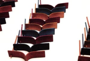
Dressing of the seam was accomplished in a number of ways. Grinding was done with adequate ventilation and a respirator, to avoid inhalation of the hazardous aluminum dusts. Seams were ground bock quickly and easily with a belt grinder and rotary abrasives in a flex shaft. "Aluminum cut" files with serration-like teeth were very effective. Abrasive papers were then used to refine the seams before anodizing. The finished forms appeared to be seamless, with the filler material matching the parent metal. A variety of fillers and aluminum alloys were tested for compatibility. All were ground, filed and finished in the same manner, then readied for anodizing using pumice and Fantastik.
The welded samples were sectioned in order to test the effects of long and short anodizing times. The standard sulfuric acid anodizing process was unaltered. The aluminum was first etched in caustic soda. At this point the crucial color match of the seam and parent metal could be evaluated, the seam often appearing slightly darker than the parent metal. Core was taken in working with these baths regarding adequate ventilation and the use of eye protection, rubber gloves and a respirator. The nitric dip seemed to remove the gray film that developed in the caustic soda. At this point, however, it was advantageous to use a soft brush and cold water to fully remove the gray slurry.
Samples were anodized for 20- and 40-minute periods. The additional 20 minutes provided an increase in the thickness of the anodic layer that would seve to reduce the possibility of color variation after dyeing. Longer anodizing time allowed the saturation of colors and, with that, greater color consistency. The filler materials held up well in the acid baths, showing no signs of etching or pitting. The 20-minute anodizing period proved successful and helped identify filler alloys not compatible to the process. The most general purpose filler, 4043, was dismissed as a possibility. A 1100 filler rod with 1100 aluminum was the most consistent and reliable. The 40-minute series carried the same results.
Conclusion
My studies indicate that torch welding with appropriate precleaning and core is the most consistent and accessible means to fabricate objects in colorable lightweight aluminum. The 1100 alloy welded with 1100 filler provided the most vibrant colors for visually seamless fabrication. I had some success in welding castings but consider these methods best applied to fabrication in sheet, patterns, die forms, spinnings, raisings and forgings.
I would like to thank Stanley Lechtzin, Vickie Sedman, Daniella Kerner, Tim McCreight, SNAG, The Lilly Foundation, Rio Grande Albuquerque, GTE/Sylvania, West Point Supply Company, The Aluminum Association, Anodizing Specialists and Force Chemicals for their support and assistance.
Matthew Hollern is an assistant professor of metals and jewelry at the Cleveland Institute of Art.
Related Articles

Nickel White Gold Welding

Laser Repair: Emerald & Diamond Ring

Welding Technology Tool Modifications Part 2

Fabricating a Free Form Opal Pendant


The All-In-One Jewelry Making Solution At Your Fingertips
When you join the Ganoksin community, you get the tools you need to take your work to the next level.
