
Translating Line Art into 3D Models in Matrix
11 Minute Read
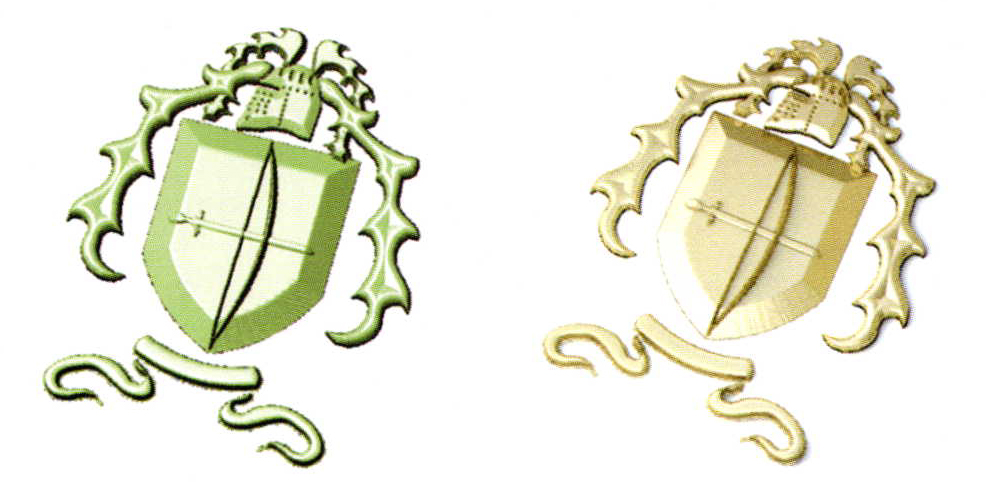
Line art, such as logos, family crests, text or numbers, cartoon characters, and even sketches can be quickly and easily translated into 3D models in Matrix for use in a variety of jewelry designs. Depending on the skill of the user, the end use of the artwork, and the requirements of the model, you may wish to select one of the three following methods, or mix these methods for optimal effect.
A Study of 3 Methods for Translating Line Art into 3D Models in Matrix
The three methods include (1) extruding closed curves to create a flat-topped design that can be used as an engraving or relief element; (2) inputting closed curves into Matrix Art to apply various cross-section shapes to the line art and complete a mesh model of the image, or (3) surface modeling, using a variety of Surface menu commands, to create a true 3-D relief model of the artwork. Each of these methods has its advantages, and each may be used at different times by the novice or advanced user depending on the desired result.
Getting Started
Each method starts with the Place Background Bitmap tool. Select the line art you wish to use from the folder on your hard drive. Then, working in the Looking Down viewport, place the upper left-hand corner of the image file at about the location and size you'll want it for the finished design. The bitmap will form a rectangle in the same aspect ratio (height to width) of the original image. That way, the bitmap cannot be skewed as you place it. Locate the lower right-hand corner of the bitmap at the size and location desired by clicking once more in the Looking Down viewport, and the bitmap will appear onscreen.
Now, using the Curve tools, carefully trace the line art design. It is a good idea, as you're doing so, to use layer colors strategically. For instance, if you trace each different shape in the line art design on a different layer color, you can right-click on the color to select all of the shapes on that layer, rather than trying to do a region-select or hold down shift for a multiple-selection in the viewports.
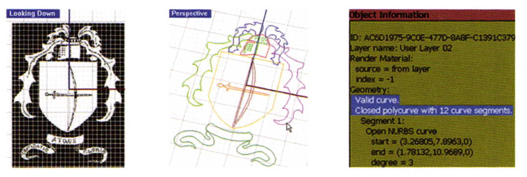
It is also very important that you use the End O-Snap to connect the ends of all of the curves that you used to make a single shape, and, when the shape is complete, Join those curves to create a single, closed curve. For the first two methods - extruding closed curves and using Matrix Art - you'll need closed curves to be successful. To check a curve that you drew to ensure that it is "closed" and "valid", click Object Information and check the report.
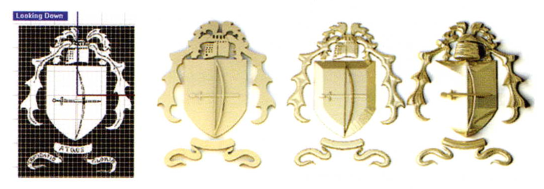
Extruding Closed Curves: The easiest method for creating 3D models from line art in Matrix is to use the From Planar Curves command, which is found in the Solids menu, to extrude the closed curves. To determine how menu, to extrude the closed curves. To determine how best to select your curves for the extrusion command, take a look at your line art: you'll now need to make some design decisions about how you want to use this image to enhance your model.
For example, you can create a simple relief image, where each shape in the design is at a different height. To achieve this, select the parts of the design you want at the same height and click From Planar Curves. If you'll be using this design as a cutter, or if you'll need to Boolean Union it to your model for use in a growing machine that can't accept intersecting solids, it's a good idea to use the "Both Sides = Yes" option that is available in the Command line during this command. That way, your model will not be "coplanar" and will Boolean successfully.
Enter the thickness you want for the design into the Command line, and press Enter. Repeat, using a new thickness (taller) for the next set of shapes, and continue until the design is complete. Or, to create "negative space" in the extruded design, select two closed curves - one that is fully inside the other - and use the Form Planar Curves command on them together. This will create holes in the design that will add visual interest to your final model.
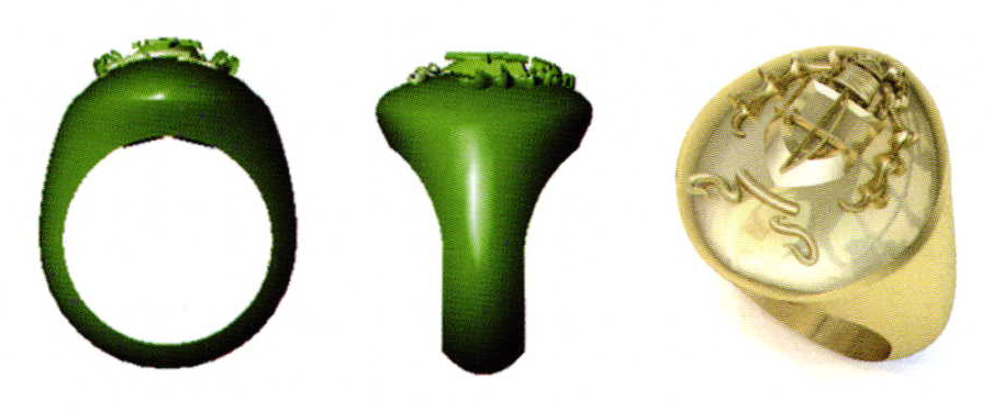
To add this line art to a model, you may wish to place it on top of a ring to create a relief pattern - using Boolean Union only if the model will be grown with a machine that cannot handle intersecting solids. Alternately, after Boolean Unioning the design together, Boolean Difference it from the top of a ring, creating an engraving of the design.
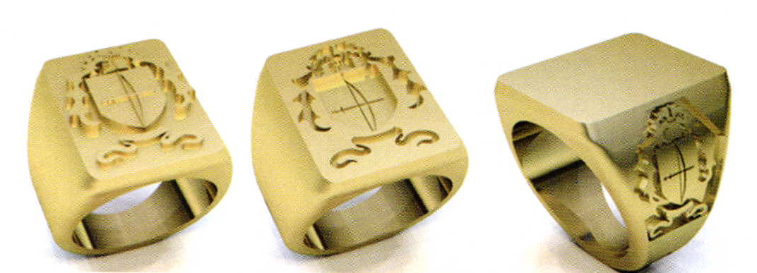
Finally, you may wish to place the design on a curved surface - such as the side shield of a signet ring. In that case, use closed, flat curves drawn in the Side View viewport to create the shape of the shield. Then, using the Project command, apply these curves to the side of the signet ring. Place the ring and the curves representing the shield into appropriate boxes in Matrix's Surface Pullback tool, assign a depth and bevel shape, and use the Cap command to create a solid "cap" surface in the shape of the shield. Position the design so that it fully intersects the shield, and, after Boolean Unioning the design together, run a Boolean Intersection on the design and the cap you just created.
Creating a Mesh
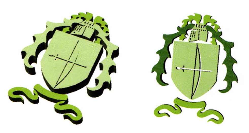
Alternately, you may prefer a different profile shape for each part of your design instead of the flat blocks created with Extrude Planar Curves. Inputting the curves into Matrix Art is a quick and easy way to achieve this. The mesh file output by Matrix Art can also be applied to different-shaped surfaces using the Bend command - a trick we'll demonstrate later on in this article.
The layer color of each closed curve making up your design is even more important to consider when inputting your model into Matrix Art. Since the layer structure is hierarchical in this builder, it's important to place the lower parts of the image onto the lower layer colors (the shield as the background for the bow and sword, for example) and the higher parts of the image (the bow and sword, in this case), onto higher layer colors.
With all of the curves input into Matrix Art, use the Layers menu in the builder to select a color to work on. Then, click on Load Profile to apply a cross-section shape to that layer. You may also assign a height to each surface on the same layer color. Finally, to change the interaction between overlapping surfaces, click on the Layers menu where the dominant (higher in the menu) color, which should be selected in pink, lines up with the column of its subordinate (lower) color until the relationship between the two is correct. Click and Create Mesh to create a single mesh surface from the design.
Or, to create mesh surfaces that can be manipulated independently of one another, input one or several curves at one into Matrix Art and perform separate Create Mesh operations for each set. That way, you can reposition each part of the mesh separately to create the look you want.
Surface Modeling: The most advanced way of translating line art into a 3D model uses commands in the Surface menu to physically model each element in the design. In this case, the curves are traced in the same way as above; however, depending on the Surface menu tool you'll use with them, you may need open curves rather than closed, to complete the image. The user must select the best modeling strategy to complete each element in the design based upon the look you want.
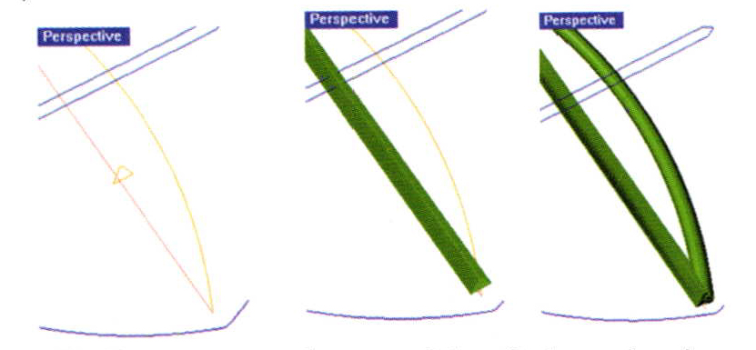
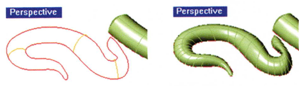
For example, to create the bow, we'll input a single, straight polyline representing the bow into Profile Placer much the same way we would a ring rail. Select a profile shape for the bow and use the dimension sliders and Set Profile to place a profile along the rail. Sweep 1 - with the straight line as the rail curve and the profile as the cross-section - is the surface tool to complete this part of the design. Use Cap Planar to close this model.
To complete the bow, Pipe is a Solid menu command that will apply a circular profile to any curve, creating a "pipe" effect. Simply select an open curve drawn to represent the bow string, and click on Pipe. Assign the same dimension for one end and the other for continuity's sake. Again, make sure the pipe is "capped".
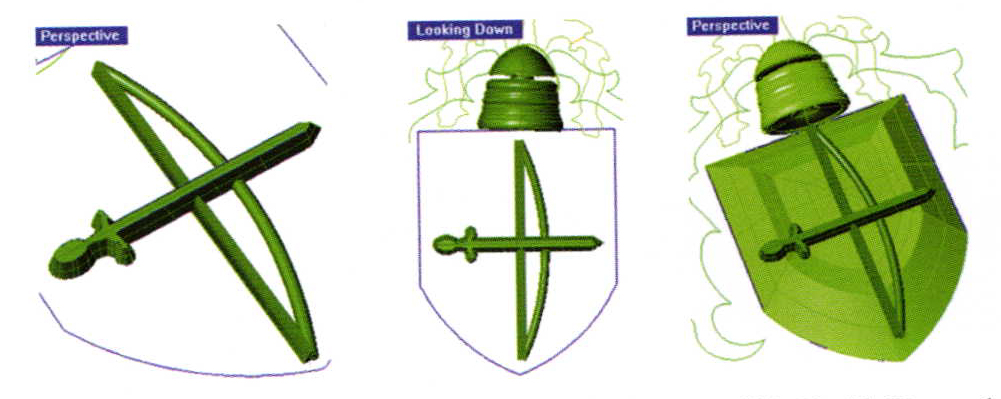
To create an angled profile with a flat top for the sword, select the closed curve used to draw it and Offset it a small distance to the outside. Select the inner curve and drag it up in space to the height desired for the sword. Loft between the two curves, making sure the seam point arrows are lined up on a long "straightaway" of the design, and Cap.
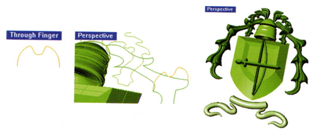
Revolve is a fun tool to achieve a true 3D object from a single profile revolved around its center point. Select the closed curve of the helmet and click Revolve. To assign the axis of revolution, click on the top and bottom of the helmet, drawing a straight line through its center. If the revolved surface is too tall for the rest of your design, select it and use the Scale 1D tool to shrink it in the Through Finger viewport to the height required for the design.
A similar tool, Rail Revolve, works in a related fashion; only the profile is revolved along any shape of curve, instead of in a circle. To use this tool to its full advantage, try it out on the shield. Draw a profile that starts along the midpoint of one half of the shield curve and extends up in the Through Finger viewport in the shape you want for the top of the shield. Select this profile and click Rail Revolve. The rail curve is the shield, and the revolve axis is straight down from the top of the profile curve:
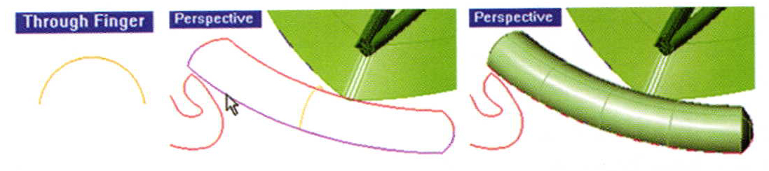
To create ribbons beneath the shield, split the closed curves you've created the "long way" this time - at the midpoint of each short end - creating two halves: top and bottom. In the Through Finger viewport, draw an Arc Direction. Using the Orient 2 Points command with "Copy" turned on; assign the ends of the arc as the "Reference Points" and the MidPoints of the ribbon curves as the "Target Points". Place only one copy at this location.
Now, using Sweep 2 - with the top and bottom of the ribbon as the rail curves - select the "Point" option and snap to one "End" where the two ribbon curves meet to indicate the first profile; the second profile is the arc you just placed; and the third profile is also found with the "Point" option at the other "End" of the two curves. The surface will appear. Cap it.
Complete the other two portions of the ribbon in the same way, using Orient 2 Points to place several copies of the arc profile along the rail curves, especially where they bow and bend dramatically, in order to keep the shape. The Near O-Snap should be used to place the first "target point" of the profile along one rail, and the Perpendicular O-Snap should be used to place the other target point so that it is perpendicular to the first. Use Sweep 2 along each profile, with the "Point" option enabled to select the End points of both curves - one on either end - as the start and end point of the surface. Cap to complete.
A similar technique can be used to sweep the vines. Only this time, let's draw a more interesting profile in the Through Finger viewport: one with a groove in the top to more closely match the original line art, which showed the veins running through the vine. Use Orient 2 Points to place this profile along each open curve, using the above trick of the Near O-Snap to place the first target point and the Perpendicular O-Snap to place the second target point.
Applying a Mesh Design to a Surface
When the flat options offered above are not exactly what you need for your design, you have another option, which can be run on any of the three models above as long as they are Mesh objects.
To transform a surface into a Mesh object, use the Utilities menu command Mesh. With your mesh design created, use the Bend command to wrap it around the surface to which you want to apply it.
Related Articles

The Form Beyond Function Exhibition

2 Tips for a Successful Jewelry Collection

Metalwork: A National Invitational Exhibition

Tony Snodgrass: Flower Ring


The All-In-One Jewelry Making Solution At Your Fingertips
When you join the Ganoksin community, you get the tools you need to take your work to the next level.
