
Lamination of Non Ferrous Metals by Diffusion
We have been interested in Mokume-gane for a number of years. The only information we could find was by the soldering of different metals, cutting in half, resoldering to increase the number of layers and then exposing those laminates by punching from the reverse side and removing those embossments or by carving drilling, etching from the top. These methods have many drawbacks; namely, air pockets, cracking and peeling. Its limitations are basically that it cannot be effectively formed or raised into complex forms. During a recent trip to Japan we visited three craftsmen who practiced Mokume-gane and worked with one of them……
21 Minute Read
"The atoms in a solid are in constant motion. These atomic vibrations coupled with vacancies in the solid allow atoms to move through the solid. The motion of matter through other matter is called diffusion. An atom may move when it attains a required activation Energy. The diffusion process may be enhanced (helped) at higher temperatures as more energy is supplied to the solid through heat energy, thereby permitting greater atomic movement in the solid.
 |
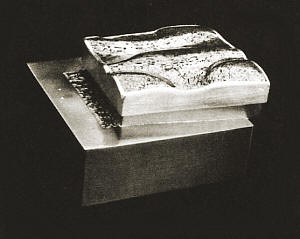
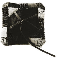
| Eugene Pijanowski & Hiroko Sato Pijanowski Box-on-a-Box No. 2 |
Diffusion can also be used to bond metals together, which is the method studied in this experiment. Atoms diffused between the layers of metal and bonded them together, resulting in a single homogenous structure.
This process may be used to join similar and dissimilar metals which are amenable to by conventional welding techniques." Mayer Engel, Materials Engineering, Purdue University
Preface
We have been interested in Mokume-gane for a number of years. The only information we could find was by the soldering of different metals, cutting in half, resoldering to increase the number of layers and then exposing those laminates by punching from the reverse side and removing those embossments or by carving drilling, etching from the top. These methods have many drawbacks; namely, air pockets, cracking and peeling. Its limitations are basically that it cannot be effectively formed or raised into complex forms. During a recent trip to Japan we visited three craftsmen who practiced mokume-gane and worked with one of them. The section Diffusion By The Traditional Method is the application used by Mr. Norio Tamagawa. H.S.P. E.M.P.
The Laminates
Copper is always used as a basic metal in Mokume-gane because of in malleability and coloring possibilities. Japanese craftsmen use copper layers of 2 to 4 torn in thickness. We used 1.6 mm copper, because of its availability. The best copper we found to use is electrolytic tough pitch, alloy no. 110 because it is relatively oxygen free and can be ordered with protective covers much like acrylic sheet so that it is scratch free.
 |
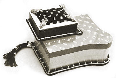
| Eugene Pijanowski & Hiroko Sato Pijanowski Box-on-a-Box No. 1 |
| Metals | When Colored with Rokusho | Malting Point | ||
| White | 9600C | |||
| White | 8930C | |||
| Yellow | 10630C | |||
| Black to Purplish Black | 10500C | |||
| Gray | 9500C (Good Quality) 9000C (Regular Quality) | |||
| Light Gray | 8500C | |||
| Dark Gray | 10400C | |||
| Dark Brown to almost Black | 10700C | |||
| Brown | 10840C | |||
| Shakudo | First Quality | Second Quality | ||
| 4.8% | 2.5% | |||
| 95.2% | 97.5% | |||
| Shibuichi | Shiro Shibuichi | Good Quality Shibuichi | Regular Shibuichi | |
| 60% | 40% | 30% | 23% | |
| 40% | 60% | 70% | 77% | |
| Kato Shibuichi | 1 | 2 | 3 | |
| 83.3% | 71.4% | 58.8% | ||
| 16.7% | 28.6% | 41.2% | ||
Kuromi-do
Kuromi-do is 1% of metal arsenic and 99% of copper. It is potentially dangerous to make, but safe to use cold. When metallic arsenic is added to molten copper it will volatilize and produce poisonous gases. We are still searching for adequate safety procedures to make kuromi-do; these should employ a good ventilation system, specific vapor masks, gloves, etc. One suggestion by Professor Harold Harrison of the Physics Department of Purdue University is to melt the copper and add the arsenic wrapped in a copper foil envelope; hopefully the arsenic will disperse and mix with the molten copper before it volatilizes.
Shakudo
Shakudo is the most useful and easiest copper alloy to make. The procedure of alloying is as follows: anneal an appropriate graphite crucible in a gas or electric melting furnace. Add copper flux (available from Paxton/ Patterson, 5719 W. 65th St. , Chicago , Ill. 60638 ) approximately 1/8 ounce per 5 pounds. When the crucible becomes red hot add metal of the highest melting point. If using highly volatible metals, such as zinc, arsenic, lead, tin, etc., to molten copper take the precautions as noted with kuromi-do. When the copper is molten or fusion occurs cover with carbon, charcoal or any commercially available melting fluxes. Carbon excludes the air from the furnace, and also absorbs any oxygen liberated from the metals during fusion. The fused mass should be constantly agitated or stirred with a carbon rod. In the meantime, prepare the ignot mold by lightly oiling or carbonizing with a candle or dirty acteylene flame the interior surfaces of the ignot mold. Prior to pouring, the ignot mold should be preheated to approximately 100 deg. C When the new alloy is at its lowest possible liquid temperature pour into a tilted mold so that the metal flows down the side wall and does not splash; otherwise it might cause blisters or pits in the ignot. If the ignot is thick and rapidly chilled, the absorbed gases cannot escape from the interior and could cause pin holes. Remove all irregularities from the edges and surface of the ignot or later cracks could occur. Planish lightly both sides of the ignot to completely align the crystals. Anneal the ignot. Adjust the rolls with a feeler gauge (used for gaping spark plugs). When rolling use light passes. Place the ignot in the center of the rolls. After each pan through the rolls the metal can be turned over end over end, this will keep the metal flat. Anneal often. Carl Hines, a graduate student in metal at Purdue University , built the gas/air smelting furnace that we used for the alloying. See Appendix A for details of construction, etc.
Diffusion by the Traditional Method
1. Materials - Some of the possible we and three metal combinations that are used in mokume-gene are copper, shakudo, kuromi do and fine silver. Mr. Norio Tamagawa usually uses eight layers of either round or square metal plates about 4 men in thickness and about 9 cm in diameter and 9 cm x 9 cm square, others use between 1 men to 4 men square sheet with the number of layers ranging from eight to twenty or more. The important thing is that the layers should be of the same thickness. Anneal and flatten. Remove all surface marks. Prepare a rusted mild steel box to contain the layers as illustrated in Fig. 1.
 |
| Figure 1 |
Mr. Tamagawa uses a thick slug of copper approximately 1/3 the total thickness of the layers as a back-up that will become the inside of his raised forms. Also prepare a piece of mild steel the same dimensions as the copper back-up, this will act as a weight; this should also be rusted. Do not touch the surfaces that are now scratch free. Chemically clean in a solution of 5 grams of potassium cyanide and 1.8 liters of water. Wear surgical, acid proof gloves. Rinse in water and dry with a lint-free cloth or paper towel. A standard acid pickle can also be used. Dry on an electric hot plate. Gas stoves are not recommended because the metal might sweat during the drying operation. Brush away any dust if necessary. Stack the metal in one of the possible combinations listed:
copper, shakudo, copper, shakudo, copper …..
copper, fine silver, shakudo, fine silver, copper, fine silver, shakudo â¦..
copper, kuromi-do, copper, kuromi-do …..
copper, fine silver, kuromi-do, fine silver, kuromi-do, fine silver …..
Place the lower melting metals between the higher metals in the sequence desired into the mild steel box. Next place the thick iron plate of mild steel on top as a weight and using thick iron wire bind the layers together as shown in Fiq. 2.
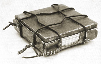 |
| Figure 2 |
The box containing the laminates are put into a hot forge that is started with a low sulphur content metallurgical coal with hard wood charcoal added to produce a reduction atmosphere. The box of stacked metals is heated to the point where the edges start to sweat (about 900 deg. C) removed and lightly tapped with a wooden hammer. If the copper and copper alloys seemed to be diffused; rapidly remove the binding wire and hot forge. If the stack contains fine silver, wait until the mass loses its red color and then forge. Reduce by forging to about 7 men or 5 mm. Annealing after every course of forging. The Pattern is produced by using a chisel called hatsuri-tagane.
The following is the procedure in making the chisel and could be applied to most metal carving tools.
- Use a piece of water hardened too[ steel about 10 cm to 12 cm in length by about 1cm square.
- Bring one end to bright red and hot forge to the shape of square ended spoon or wood gouge (see Fig. 3) and let air cool.
- Place the too] steel or nail blank in ring clamp, or small hand vise, brace it against a bench pin and begin to rough out the basic shape.
- After the rough filing, switch to a medium no 2 cut file refining the basic angles and shape of the chisel. Take a coarse emery or wet/dry silicon carbide paper, mounted on a sanding stick. and remove all file marks.
- Harden the chisel by heating the last 112″ of the cutting edge to a cherry red and plunge into cold water. To insure rapid cooling it must be moved in the water to break the insulation of the steam blanket that otherwise will form around it. It will become glass hard. To test the hardness, run a file lightly over the portion hardened; if it skips and does not cut this means the chisel is as hard or harder than the file.
- Temper by using a flame concentrated about 1/3 of the length above the cutting edge. Watch closely as the color marches or moves toward the tip or edge.
- When about 1/4″ of the tip has achieved a pale straw color immediately quench into water that should be directly below. If the tip is blue you have gone too far and must reharden, and repeat the tempering procedures. Each of the colors have a meaning: a light gray color means it is the hardest and most brittle; a pale straw color is not too soft or hard, but just right; purplish color means that it is too soft.
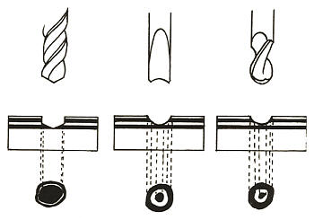
- If your chisel has been correctly tempered, use a paste polish (Happich-Semichrome) on a strip of leather, for the final stropping and polishing. Put the diffused metals into a pitch block, pitch bowl or large machinists vise. Start to carve through at least three layers using the hatsuri tagane. Remove from the holding device used. Forge out until completely flat. Repeat the sequence of carving and forging one, two or three times more observing the resultant pattern emerging. Continue forging until about 1.5 rem or any desired thickness needed. It is ready to be raised or formed. After the mokume-gane is formed and finished a coloring process using a unique Japanese patina called Rokusho can be used. Rokusho is discussed in Appendix B.
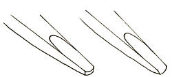 |
| Figure 3 |
Experiments in Diffusion
The decision was made to experiment with the diffusion of select non-ferrous metals utilizing an electric kiln with pyrometer. The premise was to gain heat control and also we wished that others, like ourselves, who am primarily metalsmiths could create mokume-gane with other than a blacksmiths' forge. The preparation of the metals and the placement into the previously described box will be omitted from the test descriptions. The stack of metals contained within the bound steel box are placed and removed from the preheated electric kiln with an enameling fork and a heavy iron wire screen that was bent into an u-shape. Throughout the remainder of this paper when copper is mentioned it is electrolytic tough pitch, alloy no. 110
 | |||
| Figure 4 | Figure 5 | ||
 |
| Figure 6 Mokume-Gane, 1-77 Eugene Pijanowski, Hiroko Sato Pijanowski |
Test I
Six layers of copper each being 1.7 ram x 50 mm x 5 men were placed into a preheated (1000 deg. C) electric kiln for 20 minutes and then gradually the heat was brought up to 1050 deg. C. The copper melted and fused to the steel box and steel plate. (Fig. 7-1). The pyrometer was not accurate. Tests were run using ceramic cones to calibrate the pyrometer. (TempilO, Hamilton Blvd., S. Plainfield, N.J., 07080, are producers of temperature indicators, protective coatings & markers; these may also be of use.)
Test 2
Copper of the same number and dimensions as in Test 1 were placed into a preheated (955 deg. C) electric kiln for 10 mins. The copper melted, but not as badly as Test 1. We were begin rung to learn the characteristics of the pyrometer and kiln. The copper fused to the iron cover plate. it was cut in half and forged to see how well the copper and the iron were fused. Fig. 7-2 shows the copper mushrooming out deforming quite radically, but the iron plate remains relatively unaffected and still fused to the copper layers.
 |
| Figure 7 |
Test 3
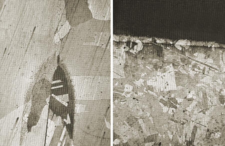
Copper of the same number and dimensions as in Test I were placed in a preheated (625 deg. C) electric kiln and brought up to 920 deg. C (time elapsed from placement into kiln and temperature achieved was 45 mins.). and held for 6-7 mins, gradually increasing the temperatures, observing the stack through the peephold for 4-5 rains. and removed from the kiln when it seemed to be sweating. It was then placed on a hard fire brick and tapped with a wooden hammer. Immediately after tapping the lamination was removed from the box and hot forging commenced; it looked diffused so it was cut in half; one half filed, sanded, polished, etched with ferric chloride to bring out the crystalline structure and photomicrographed (BOX) by Mayer Engel (Fig. 4) describes what has occurred. "Figure 4 shows an area near the edge of a sample where the material of two subsequent layers has oxidized from the air within the furnace. The gap between the two layers begins to break up where grains have actually begun to grow over it, producing a homogeneous structure".
The other half was forged out to 2 mm, a piece 7 men x 15 rem, was cut out from the larger piece cast into plastic; sanded, polished, etched and photomicrographed, (BOX) by Mayer Engel, in approximately the middle of the piece. Figure 5 shows a grain growth where layers had been previously; all except the top most layer where oxidation has occurred in some areas.
Test 4
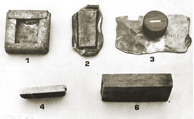
Copper of the same number and dimensions as Test 1 were placed into a preheated (875 deg. C) electric kiln and held at that temperature for 30 mins. The temperature was brought up to 920 deg. C and held for 5 mins., then increased to 970 deg. C for 2 mins. The corners melted. This piece was cut in half, filed, sanded, polished and etched. The intrusion of oxides could be seen into the center of the mass in some areas. (Fig. 7-4)
Test 5
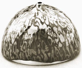
Four layers of copper each being 1.7 ram x 50 mm x 50 arm were alternately stacked with four layers of shakudo each being 1 rare x 50 ram x 50 mm, with back-up copper 6 mm x 50 ram x 50 men, the total being nine layers. The laminates were placed into a preheated 745 deg. C electric kilnbrought up to 825 deg. C and heat soaked for 15 mins.; after which the temperature was brought up to 875 deg. C and held for 30 mins. and then gradually up to 920 deg. C where meeting was observed. The lamination was removed from the kiln, tapped and hot forged to 8 men. The pattern was started with the hatsuri-tagane; forged again to 6 mm and carved. The forging and carving was repeated 3 more times to a thickness of 1.7 mm x 120 mm x 120 rem and raised (Fig. 6).
Test 6
Eight layers of copper each being 1.7 mm x 75 mm x 75 mm plus a back-up piece of copper 6 mm x 75 mm x 75 mm were placed into a preheated (875 deg. C) electric, kiln and held at that temperature for 30 mins. The temperature was brought up to 945 deg. C, held for 10 mins. gradually increasing the temperature and when sweating was observed removed and lapped. Diffusion had occurred.
Test 7
Four layers of copper each being 1.7 rum x 75 mm x 75 mm were alternately stacked with 5 layers of kuromi-do of the same dimensions with a back-up copper layer 6 mm in thickness, the total being 10 layers. The same procedures were used as in Test 6. Good diffusion. The carving technique being very laborous and time consuming, we decided to search out mechanical aids. The first was a common drill; but it produces a limited, tight pattern. Because of the high angle of its contour and point. After checking out horizontal and vertical mill cutters we located a tool which creates the same low angle cut as the hatsuritagane; the Two Flute Ball Endmill (available from Rutland Tool and Supply, 501 W. Washington Blvd., Montebello, Calif., 90640). Carved and forged three times to a thickness of 1.6 mm x 180 mm x 180 mm and in the process of being raised.
Test 8
Four layers of fine silver I mm x 75 mm x 75 mm were alternately stacked with three layers of copper (1.7 mm) and two layers of kuromi-do (1.7 mm) for a total of nine layers. Fine silver was used because its melting point is closer to the copper and copper alloy used and also for its malleability. Fine silver was placed between each of the other metals. Refer to Part 11, Section 1. The difference in thickness between fine silver and the other metals was because of its availability. The stack was placed into a preheated (800 deg. C) electric kiln for 30 mins. and brought up to 875 deg. C and removed 7 mins. later. The silver melted. Now trying to salvage as much as possible.
Test 9
Same metals and stacking sequence as Test 8. The stack was placed into a preheated (750 deg. C) electric kiln for 30 mins. and brought up to 790 deg. C and removed after 7 mins. The bottom layer of fine silver, between the copper base layer and bottom layer of kuromi-do, started to melt. Fair results. In the process of salvaging as much as possibleFine silver should be of the same thickness as the other metals used.
 |
| Figure 8 |
Conclusion
This report is incomplete. Diffusion is technically involved and requires numerous tests. The character of the electric kiln by direct observation of the meeting of metals or diffusion temperatures is the only way of achieving any semblance of success. Copper to copper is recommended as a starting point. Them is room for more research. The hope is that this report will be a point of departure for others to follow. Tests will continue in terms of time and temperature sequences. Recommended time and temperature sequences for copper to copper alloys. Place the stack of metals into a preheated (825 deg. C) electric kiln for 30 mins., bring up to 875 deg. C for 15 mins. and gradually increase temperature to 920 deg. C and observe for sweating; the maximum temperature should not exceed 950 deg. C. Recommended time and temperature sequence for including fine silver into the stack, between every layer of the other metals used. Place the stack of metals into a preheated (750 deg. C) electric kiln for 30 mins., bring up to 790 deg. C and observe for meeting to occur.
 |
| Eugene Pijanowski & Hiroko Sato Pijanowski Shell-On-Quilt kimono silk, shell and copper; 4.5″ |
APPENDIX A
Smelting Furnace
An adequate smelting furnace must fulfill the following requirements: a temperature of approximately 2000 degrees F, a quick and uniform heating of the smelting crucible, a controllable furnace atmosphere to minimize slag formation, and a furnace chamber that is accessible to easy placement and removal of the crucible.
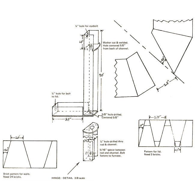
A gas furnace allows for a controllable atmosphere. A circular chamber with the single burner set on a skewed line provides a spiral flame path which surrounds the crucible for uniform heating. A lid with a swivel hinge provides access from the top and acts as the flue. A chamber 10″ in height and 8″ in diameter allows for a No. 12 crucible which is capable of holding 36 pounds of bronze.
Construction :
The furnace is made of standard K-26 soft firebrick - 4.5″x2.5″x9″ cut to form a 12-sided polygon. The bottom of the furnace is a 2.5″ layer of brick. The sides are four 2.5″ thick rings. Each ring consists of 12 trapezoidal pieces, two of which can be cut from one brick. The whole assemblage is set into a heavy metal container with a minimum inside diameter of 18″. A shortened heavy duty garbage can was used in which the bottom was reinforced with a 14 gauge steel disk. The space between the brick and metal wall was filled with vermiculite insulation and tamped firmly to hold the brick in a stable configuration. The burner port is an opening 2.5″ x 2.5″ in the lowest ring made by cutting short two of the pieces. The port should angle approximately 20 degrees off the radius. The burner used in this case was a natural gas air torch already available in the workshop. Any burner or torch with a 50,000 to 100,000 BTU output can be used and a suitable clamp or bracket made to hold it in place The end of the burner should not extend into the port or else overheating and corrosion of the burner tip might occur.
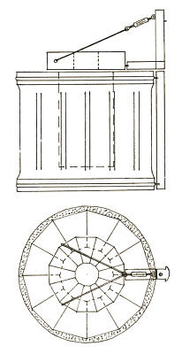 | Side View |
| Top View |
The lid is made of 12 trapezoidal shaped pieces to make an 11″ in diameter polygon with a 4″ hole in the center. A 26 gauge steel strap 2.5″x 36″ with two hose clamps rivited to the ends, acts as a compression ring to hold all the bricks together. A hole is provided for a 1/4″ bolt which fastens the lid and the compression ring to the hinge assemblage.All exposed brick surfaces should be coated with a super duty refractory cement to protect from brick particles contaminating the melt.
The hinge is two constructions; a steel rod fastened to the steel jacket with a "stop" even with the top of the furnace, and an assembly which fastens to the lid compression ring. The lid and hinge assembly slip onto the rod which extends above the top of the furnace. A turnbuckle is fastened to the top of the lid hinge and a cable run from it to two points of the lid compression ring. This provides a 3 point support and allows for adjustments of the lid to keep it clear of the furnace top. Additional washers are used as spacers between the lower and upper hinge. It is important that the steel jacket be strong enough to support the hinge.
There is quite a bit of leeway in the burner positioning The flame should hit the furnace wall, not the crucible. A good spiraling flame can be seen from above.
APPENDIX B
Coloring
In Japan a commercially available patina called rokusho is used. It is impossible to import into this country on a commercial basis because of the nature of its ingredients which are considered to be poisonous. Rokusho is an etchant and creates different oxidizes on the surface of the metals laminated in the process of mokume-gane. Refer to chart in Part 1 for colors achieved with rokusho. Rokusho has been analyzed to contain:
![]() copper acetate Cu (CH3C00)2.H2O - 30 grams
copper acetate Cu (CH3C00)2.H2O - 30 grams![]() calcium carbonate CaC03 - 10 grams
calcium carbonate CaC03 - 10 grams![]() sodium hydroxide NaOH - 10 grams
sodium hydroxide NaOH - 10 grams
The above is dissolved into 750 ml of water (filtered or distilled) and then it is left to stand for a week or more. The container should be glass, plastic or copper. Drain the top water. This is rokusho! To a copper or pyrex container add the rokuSho with 4.5 liters of distilled or filtered water and 20 grams of copper sulphate. Bring to a boil. Grind, long, white raddish known as daikon and add 5 parts of water. Place a large container of water near the solution of rokusho. Remove all fire scale before the piece is to be colored. Boil the piece (if buffed) in water to remove the surface grease and oils. Clean in a strong pickle solution or in a solution of 5 grams of potassium cyanide with 1.8 liters of water.
- Cover the object with the raddish solution and dip into the boiling rokusho keeping the piece constantly moving for ten minutes. Remove from the solution and immediately immerse in the nearby container of water, to avoid water spotting or from particles of rokusho drying on the surface of the piece.
- Repeat step one several times until the coloration is achieved. It usually takes 30 minutes to one hour. Copper should turn reddish brown, shakudo a bluish black and kuromi-do a dark brown and any silver surfaces should remain uncolored.
Another solution: copper acetate - 3 dwt; copper sulphate - 2 dwt; water 1 liter. The above is dissolved and brought to boiling. The procedure is the same as the above. Degrease your hands and wash the object in ammonia and detergent soap solution of equal parts. This solution is not as satisfactory in achieving a reddish brown on copper, but will color shakudo and kuromido. After using either of the two above solutions to achieve coloration on an object of mixed metals, apply a coat of bees-wax or any wax that contains no cleaners, by warming the piece on a hot plate, wiping off any excess wax and polishing with a clean, lint free cloth.
Acknowledgements
We would like to give our deep appreciation to all the Japanese metal craftsmen and artists who have inspired our work; in particular Mr. Norio Tamagawa for his unselfish giving of his precious time and knowledge. In the text a few others are specifically mentioned. A deep thanks to Dr. Cyril Stanley Smith, Institute Professor Emeritus of the Massachusetts Institute of Technology, for his informative correspondence.
Hiroko Sato Pijanowski
Eugene M. Pijanowski
May 3, 1977
Bibliography
- Gee, G., The Goldsmiths Handbook Crosby, Lockwood and Son, 7, Stationers' Hall Court , Ludgate Hill, London , 1903.
- Gowland, William,Metals and Metalworking in Old Japan , Japan Society, London , Vol. 13, 1914-1915.
- Hiorns, Arthur H., Metal-Coloring and Bronzing, Macmillan and Co., London and New York , 1892.
- Hiorns, Arthur H.,Mixed Metals, Macmillan and Co., Ltd., London , 1901.
- Niiyama, Chokin Tankin No Giho I, Nihon Kinko Sattka Kyokai, Tokyo ,1969.
- Smith, Cyril Stanley, "Sectioned Textures In The Decorative Arts" reprinted from: Stereology, proceedings of the Second International Congress for Stereology, Chicago , April 8-13, 1967, Springer-Verlig, New York, Inc., 1967.
Related Articles

Damascus and Pattern Welding

Electric Kiln Fired Mokume Gane Part 1

Laser Mokume Gane

The Seven Korean Metalsmiths


The All-In-One Jewelry Making Solution At Your Fingertips
When you join the Ganoksin community, you get the tools you need to take your work to the next level.
