
CAD/CAM: Creating a Class Ring – Part 1
5 Minute Read
Advanced Jewelry Technologies (owned by this author) and Rio Grande are introducing a new CAD CAM system designed to make it far easier to make class rings, family crest jewelry, and corporate jewelry. This kit not only streamlines the concept and presentation, it also delivers a beautiful product in at least half the time it has taken with other systems.
The total expense of current CAD CAM manufacturing starts with the fixtures necessary to just hold the parts in the CNC Mill. Many times these fixtures have to be made to fit the mill. They can be confusing and expensive to make. Sometimes there are several steps to cut the metal molds that are used to inject the wax. This may involve more than one fixture change on the mill to get the part to work. Changing holding fixtures takes up a lot of time. The calibration alone could be off a few thousandths of an inch and screw everything up.
My new CAD system has one holding fixture secured to the mill. It is left in to do all tooling with no removal or change of holding fixture. The parts are bolted into the holding fixture for all tooling. The replacement plastic masters are also inexpensive. The molding process costs under $5.00 per mold because the shell molding system can be used over and over again. The present metal molding process is expensive and unforgiving. Many class ring molds, when all the expenses are added up, can total hundreds of dollars.
Accordingly, my costs to produce a piece were cut dramatically. With machine time being the primary expense, I worked on several other projects while the part was being cut.
If I price my machine time at $15.00 per hour, this model cost under $75.00 to produce. However, the part is the least of the expenses. There are a minimum amount of fixtures needed. Extra fixtures can raise the price to thousands of dollars. The holding block was really all that was needed. And that just fit into the vise on the mill, which kept set up to a minimum.
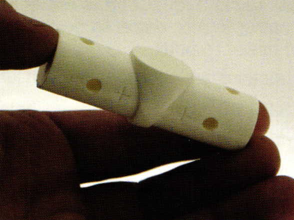
With a variety of blank styles to work with, I had no trouble producing a model for review in about four hours. This was a positive design anyone could look at and edit, unlike tooling a negative into a metal shell, which is the current process. The design utilized ArtCam for the surface relief and a Max NC 10 for the cutting of the part. The actual CAD time only took an hour. The more efficient your skills are on a surfacing program, the faster you can produce the jewelry. Any surfacing program should work. The milling with the low end Max actually needed two cutting paths on each cut surface due to the relatively slow speed ofthe mill. A spindle speed of 15,000 rpm will increase the productivity of this process.
Cutting plastic has its definite advantages. The cutter provided in the kit should last much longer than others because it is cutting hard plastic, not metal. After cutting several parts, the cutter is still in good condition. Detailing down to .002″ was easily attainable.
Joy MacDonald produced the following photo journal and instructions. Her presentation skills and talent are most appreciated.
Ring Making
This step-by-step instruction manual guides the process. With a core product to produce, endless variations are possible. The system consists of two components. These components are ring making and bezel making. All fixtures for the process are included in the kit as well as an accessories kit. All you need is a surface design tooling program and a CNC Mill. For the required hardware you need to refer to your surfacing software requirements.
Select ring style from six masters. Load surfacing software. Load AJT@ CD-ROM. Select side A, top surface B, or side surface C. Do a "Save As" now.
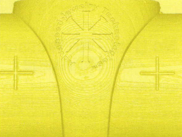
Set left cross to zero in program. Create relief on selected surface. SurfacesA, B, and C can be done one after another. Be sure to do a "Save As" after each design. Note: top surface B is a flat ring top. Each bezel file is separate. Cross marks on each end of blank surface calibrate part on mill with digitized part in program. Run a tool path.
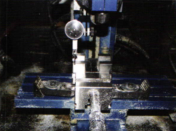
Secure V Block for parts onto CNC Mill bed. Align V Block along x-axis to ensure V Block is straight and true on mill. Secure travel index dial to spindle. Move spindle back and forth to establish a true path. Adjust V Block with hold down clamps until true and secure. lf V Block is secured with vice, align vice the same way.
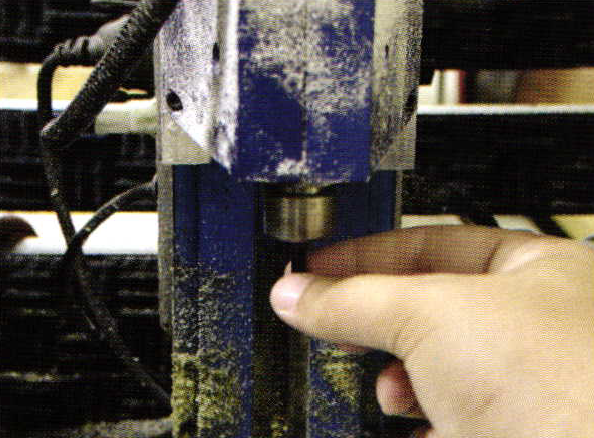
Secure cutter into CNC Mill collet. A drill stop is not necessary with ring part cutting.
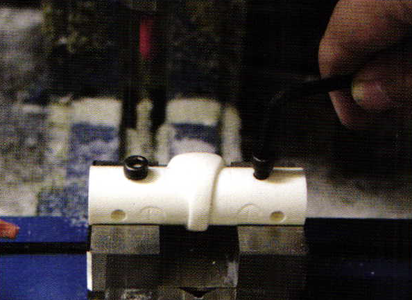
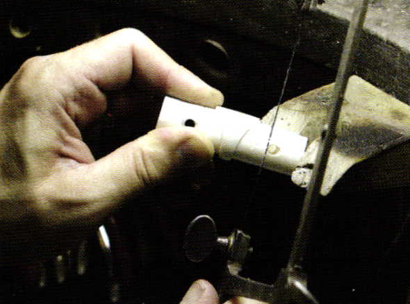
Bolt master ring blank into V Block. To establish zero, jog table bed to align cutter to fit into center of left cross mark and zero all axes. Touch off is not required if done carefully. Place cutter in gap of cross marks. lf you are concerned about breaking the cutter, turn mill on and keep spindle turning when you calibrate. This is usually done with magnification.
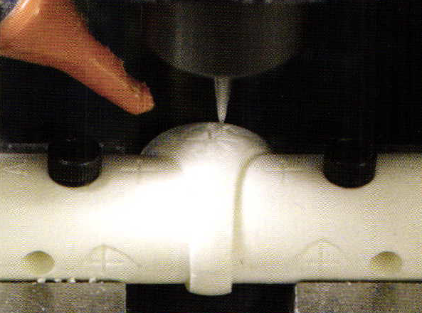
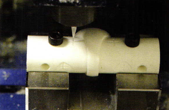
Import Side A tool path into CNC Mill Program. Cut side A and inspect while part is still secured in V Block. Cutting speed is mill based. Some better mills take less time. Better mills have faster spindle speed and cutting capacity. 10,000 rpm and above is recommended for proper cutting of material. Slower mills work but may require two cutting paths to remove material. Remember, once the part is removed from V Block, exact calibration will not be possible. When cutting material, no cutting fluid is necessary.
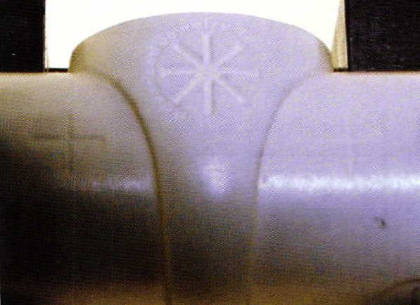
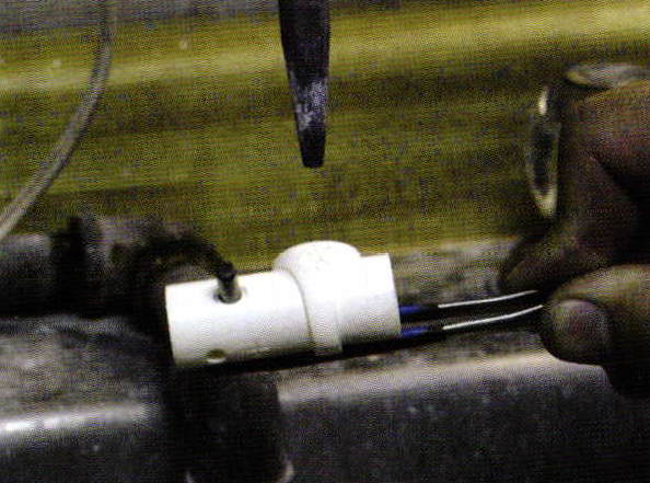
Inspect part when finished. Leave in V Block, blow off with air jet, and inspect with magnification.
Cut resin blank at cross mark to fit into mold frame. File resin blank to fit into mold frame. Insert alignment dowel pin into hole in arbor. This will center ring in mold frame.
Steam part. If steamer is not available, a small brush and ultrasonic cleaning willwork. Plastic model material is very durable.
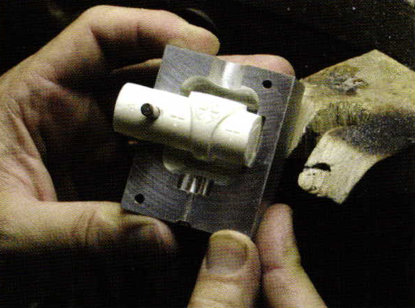
After tooling, place part into AJT mold frame. See mold making for complete process.
Creating the Bezel will be covered in this issue of BENCH magazine.
Related Articles

Naum Slutzky Jewelry at the Bauhaus

Claus Bury Architectonic Propositions

Hints on Making Tubing
Jewellers’ Objective Attitude Towards Designing


The All-In-One Jewelry Making Solution At Your Fingertips
When you join the Ganoksin community, you get the tools you need to take your work to the next level.
