
Box Clasp Fabrication
One of the most important types of closures used in jewelry is the box clasp. This clasp and its many variations are usually built into jewelry such as bracelets, necklaces, and chains. However, as an exercise, this project demonstrates the fabrication of a sample clasp as an independent unit..
9 Minute Read
One of the most important types of closures used in jewelry is the box clasp. This clasp and its many variations are usually built into jewelry such as bracelets, necklaces, and chains. However, as an exercise, this project demonstrates the fabrication of a sample clasp as an independent unit.
This project relies on precision measuring, filing, sawing, soldering, fitting, and assembly. Construction of a box clasp requires measuring with dividers, slide calipers, and a machinist's square. Procedures include creasing and folding the sides to form a rectangular box.
If such a clasp were to be built into a heavy curb chain bracelet, the roof of the clasp would be left off. Two links of the chain would be soldered together, with one of these cut in half. The link and a half would be thinned from below to hold the housing, with its opening flush with the cut in the link. The tongue would be soldered to the half link, with the trigger extended taller, through a slot in the chain.
1
The box clasp is composed of six pieces of metal: The four walled housing is folded from a single strip, plus the tongue, trigger, end plate, floor, and roof (Figure P18-1).
 |
| P18-1. Diagram of the box clasp |
2
The first component is the 10 by 15 mm rectangular housing. It is made by creasing a strip of metal and then folding the corners into 90° angles. From 0.7 mm sheet, cut a strip 2 mm wide and 55 mm long. It must be flat and straight, with parallel sides. The ends need not be square. Clean the strip with an abrasive pad or paper.
3
Scribe a small mark about 2 mm from one end of the strip. Use a pair of dividers to lay out the other corners, which will be filed and folded. Set the dividers at 15 mm and place one point lightly into the scribe mark. Swing the other point across the strip, making a second mark. Reset the dividers at 9. 8 mm, and make a third mark. Reset the dividers to 14.8 mm and make a fourth mark. Lay out the final side with dividers set at 10 mm (Figure P18-2). The 0.2 mm is subtracted from the middle sections, in order to compensate for the metal left by not filing completely through at the ends of those sections.
 |
| P18-2. Layout of the walls |
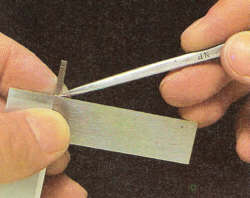
4
Machinist's squares are valuable tools for laying out perpendicular lines and for checking right angles. Hold the strip against a machinist's square with one of the scribe marks aligned with the perpendicular leg of the square. Use a scribe to make a straight line at this mark (Figure P18-3). Repeat this process and mark all five of the layout lines.
 |
| P18-3. Scribing a right angle against a machinist's square |
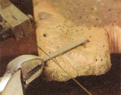
5
To prepare the corners for creasing (also called scoring), saw absolutely straight on each of the five lines, about halfway into the thickness of the metal (Figure P18-4). Make sure that these lines are straight and perpendicular. Some goldsmiths use separating disks mounted in a flex shaft for rapid scoring and creasing.
 |
| P18-4. Sawing to start the creases |
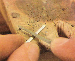
6
Use a triangle needle file to increase the depth of the creases to about three quarters of the metal thickness (Figure P18-5). Be sure to file straight and evenly, alternating among all of the creases so they advance equally.
 |
| P18-5. Beginning the creases with a triangle needle file |
7
Finish the creases with a square needle file, increasing the depth to 95 percent of the thickness (Figure P18-6). The deeper the creases are and the thinner the metal is, the sharper the corners and the more accurate the dimensions of the box will be. The metal is weak at these creases and can break if not treated with care. To avoid breaking while filing deeply, hold the metal strip flat on a bench top, near the edge, and bring the square needle file to the metal. Let the square needle file go all the way through the metal at the two end creases, so that the excess breaks off. The other three creases should be so deep that faint lines are visible on the back of the strip.
 |
| P18-6. Finishing the creases with a square needle file |
8
Next use a plastic abrasive pad to clean all surfaces, blow or wipe away the dust, and then flux the three creased corners before bending them. Carefully fold the housing into shape. The two ends should come close together but need not meet perfectly at this point, because this (open) corner will be soldered in a separate operation. Check the corner angles by holding the folded housing up against the right angle of a machinist's square, and correct as indicated. Place a small snippet of hard solder on each of the three creased corners and solder (Figure P18-7). Quench, pickle, rinse, dry, and clean with an abrasive pad.
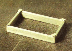 |
| P18-7. Folded box with solder in place |
9
Check the housing for accuracy with a slide caliper. Adjust the ends to meet properly. If there is a gap, fit a sliver of metal into the open corner and solder. If there is too much metal, carefully file away the side that has an excess, maintaining the correct 45° angle on both ends. Solder the last corner with a small snippet of hard solder. Do not file the sides of the housing, but gently sand the top and bottom edges against abrasive paper held on a flat surface. The housing should sit flat on a steel plate.
10
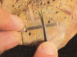
Set the dividers at 1.4 mm and use them to scribe a line across one of the 10 mm walls. Saw and then file the opening for the tongue, removing the metal to the mark, leaving 0.6 mm of metal on the wall. File the sides of the opening flush with the inside of the 15 mm walls. Check the height of the opening with the depth gauge of a slide caliper (Figure P18-8).
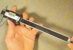 |
| P18-8. Using a digital slide caliper to measure depth |
11
To make the tongue, saw a strip 9 mm wide and 40 mm long from 0.7 mm sheet. With the machinist's square as a guide, scribe a perpendicular line across the middle and then place the strip into a smooth jaw vise, with the scribed mark at the edge of the jaws. Gently fold the strip to a right angle on the line. Remove the tongue from the vise and complete the fold all the way. Use a mallet to close the metal tightly. The thickness of the folded tongue should measure 1.4 mm.
12
File the sides of the tongue parallel, and perpendicular to the crease, so that the tongue fits exactly inside the housing. Slide the tongue into the carved opening. Inspect the fit and adjust the tongue to remove any contact areas that prevent it from entering all the way. With the tongue inserted through the filed opening into the housing, scribe a line across the top of the tongue along the inside of the opening. Remove, and with a knife, wedge the tongue open about 1 mm. Carefully saw just outside the scribed line, without damaging the bottom. File the top to fit, so that it clicks into place snugly within the opening of the housing.
13
Place the housing, with the filed opening up, onto a piece of 0.7 mm sheet, which will become the roof. Flux and solder. Then quench, pickle, rinse, and clean. Saw the excess from the roof, leaving about 0. 5 mm all around.
14
Make the trigger, the. part you actually push to open the clasp, from 2 by 3 mm rectangular stock or from 2 mm sheet. Cut a notch into the end, 0.7 mm deep, leaving 0.7 mm at the edge. Solder the trigger into place, centered perfectly on top of the short end of the tongue (Figure P18-9). The back of the trigger should overhang the end of the tongue by 0.7 mm. Quench, pickle, rinse, dry, and clean.
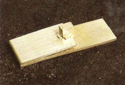 |
| P18-9. Tongue and trigger setup with solder |
15
Slide the tongue into the housing as far as it can go before the trigger stops it. Mark the width of the trigger on the roof of the housing. Measure and transfer the length of the trigger with a pair of dividers. ]Pierce out a precise rectangular notch to accommodate the trigger. This is important, so be extra careful nor to remove too much metal too quickly. Work slowly and check the opening often for accuracy. Use flat and barrette needle files to make flat sides and crisp corners in the notch so that it fits the trigger as tightly as possible (Figure P18-10). Stop when the tongue/trigger assembly clicks into place.
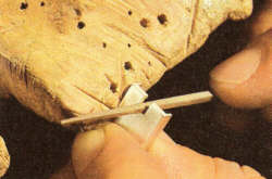 |
| P18-10. Filing a notch in the roof for the trigger |
16
Trim the top of the trigger to the specified height of 3 mm. Insert the tongue into the housing and check the fit, adjusting as needed so that the trigger slides snugly into the carved notch (Figure P18-11). With the tongue inserted all the way into the housing, file the back of the trigger flush with the end of the housing.
 |
| P18-11. Housing with the tongueltrigger assembly |
17
Solder the housing assembly onto a piece of 0.7 mm sheet for the floor. Leave the floor slightly oversized for now. Insert the tongue/trigger into the housing. Mark a line on the lower tab of the tongue flush with the outside of the housing. Set a pair of dividers at 1 mm. With one leg against one side of the tab, drag the dividers along, scribing a line at I mm. Repeat on the other side of the tab. Saw and file the sides of the tab to the marks, leaving a small excess along the short line that marks the depth to which the tab enters the housing. Insert the tongue into the housing and file the notches in the tab flush with the end of the housing.
18
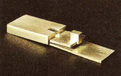
Drill and pierce a rectangular slot in a piece of 0.7 mm sheet, to precisely fit the tab end of the tongue (Figure P18-12). Woodworkers would call this rectangular hole a mortise and the tab a tenon. With the tongue clicked into the box, slip the end plate over the tab. Check the fit and adjust as necessary. File the housing to square all sides, taking care not to remove any more metal than absolutely necessary. Use a machinist's square to check for right angles, correcting as needed.
 |
| P18-12. Filing a slot in the end plate, with the completed housing and the notched tab of the tongueltrigger in the background |
19
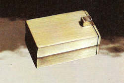 |
| P18-13. Finished box clasp |
Remove the tongue from the housing. Coat the trigger with antiflux to prevent the solder from flowing and thereby freezing the back of the trigger to the end plate. Slide the end plate over the tab. Hold the assembly in a third hand and solder it in the position established. Quench, pickle, rinse, dry, and clean. File away the excess tab flush with the end plate. File the end plate flush with the rest of the box. Sand the entire box clasp with 240 grit and then 400 grit paper to finish. Inspect and adjust areas that hang up or impede the clasp's closure or audible click (Figure P18-13).
Related Articles

Basic Hinge Making Technique

All About Hidden Hinges

How to Make Earring Posts by Hand
Special Repair Work


The All-In-One Jewelry Making Solution At Your Fingertips
When you join the Ganoksin community, you get the tools you need to take your work to the next level.
