
The Benefits of Multiple Cell Electrolysis Technology
6 Minute Read
Every goldsmith needs a precise, energy rich gas flame at his workplace. Compressed gas cylinders offer one opportunity for this. However, the just-in-time (JIT) gas production using electrolytic gas generation is a better and safer alternative. But how does this technology work? What must user know and take into consideration before purchasing this kind of system?
Electrolytic gas generators do not store the gas they produce. They are so-called just in time (JIT) producers. Accordingly it is not possible to draw unlimited quantities of gas per second from such a JIT source, as it for instance would be possible from compressed gas cylinders. This limited gas volume release makes the electrolytic gas generators extremely safe. Enormous amounts of energy are stored in compressed gas cylinders; once as mechanical energy due to the pressure of up to 250 bar and additionally also as chemical energy stored in the combustible gas itself. Anyone who has ever seen how a gas cylinder with a broken off valve has blown through a brick wall or how a small propane gas cylinder can demolish an entire house will show an appropriate respect for these ticking time bombs.
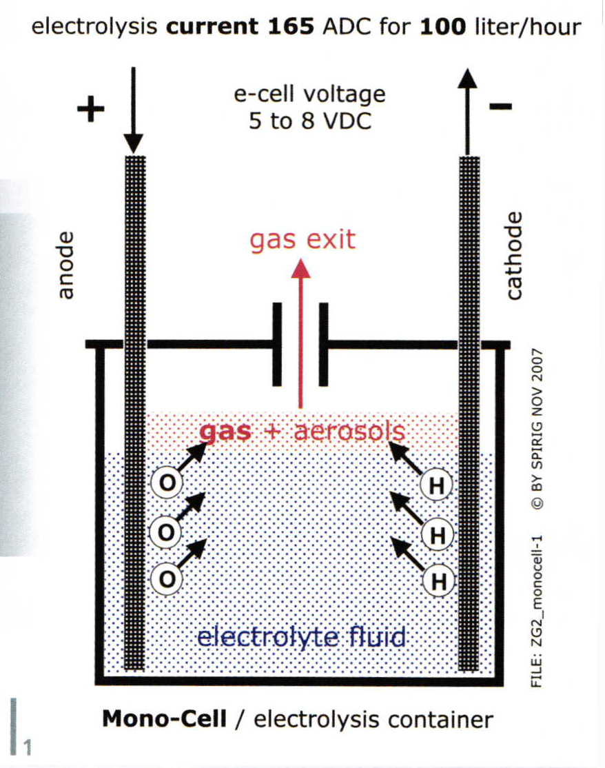
Electrolysis, be it monocell (two electrodes) or multi-cell (three and more) follows the elementary physics law defined by Faraday: In order to produce by the electrolysis of water (H2O) a volume of 100 liters of a gas mixture consisting of two parts hydrogen (H) and one part oxygen (O), a direct current of 165 amperes must flow for the period of one hour between two electrodes submerged in electrolyte fluid. This decomposes precisely 54.6 grams of water. The gas volume produced (electrolysis) or deposited material quantity (electroplating!) behaves strictly proportional to the current intensity and time duration.
The goldsmith, usually with some basic knowledge on electric issues, will immediately take notice of the required high direct current (dc) of 165 amperes. Such high currents will cause in electric conductors (cables, secondary coil on the transformer, current rectifiers) exposed to those high currents serious heat losses, means temperature levels. Heat losses increase with the square of the current intensity, means doubling a current will quadruplicate the heat losses.
To squeeze these 165 amperes through a cell, a certain voltage (depends on cell design) must be applied to overcome the electrolysis cell resistance. Faraday dictates that in a single cell (fig. 1), the 165 amperes will be able to create a maximum of 100 liters gas per hour (l/h). This 100 l/h gas flow permits the creation of only one weak flame. In order to solder or even melt a mass of 10 or more grams of gold or even platinum, the goldsmiths will preferably have access to flame strengths corresponding up to 200 and more l/h.
To produce at a 200 l/h rate a mono-cell electrolyser requires an electrolysis current of 2 x 165 amperes = 330 amperes. To function reliably, this high current level needs cables as thick as a thumb, very solid electric connections and a series of additional precautionary design steps. Remember: the starter current in a passenger car easily reaches for a few seconds 300 amperes during the crank up process. The electrolysis gas generator now would have to operate continuously on such 330 amp levels and not just intermittent for a few seconds.
To continuously handle these high current levels, the electrical resistance values of the various electric components must be kept as low as possible. The electrical energy is usually taken from an ordinary 230 volt outlet. The primary side of the transformer is fed from there, the current in the primary winding is still small.
The mono-cell operates on a low voltage between 5 to 10 volt. The purpose of the transformer is to transform the 230 volt down to the required 5 to 10 volt and the very high 330 amp current needed for the electrolysis process. With these extreme current levels the heat loss problems start and are limited by using thumb-sized high current cables in the transformer coil itself, from the transformer to the current rectifier (electrolysis functions only with a rectified current = DC), then to the electrolysis container and finally inside this container from the positive electrode (anode) through the electrolysis bath to the negative electrode (cathode). The electrolyte fluid between the electrode plates is a poor conductor and as a consequence the fluid temperature will be quickly driven up by the heat losses developed in the fluid.
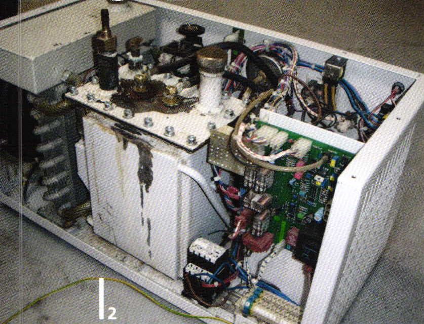
The cell resistance depends on the following factors: the chemical composition of the electrolyte fluid, its temperature (the resistance drops slightly when warmed, the chemical aggressiveness rises exponentially). The electrode surface and the distance between the electrodes. Pure (distilled or demineralized) water (to be split into hydrogen and oxygen) is an electric insulator, in other words a none-conductor. In order to give water electrical conductive properties, it is mixed with a conductive carrier fluid, for example potassium or sodium lye. Both are corrosive liquids. The high dc current flow through the electrolysis bath heats the fluid intensively and in extreme cases may even make it boil. The gas components produced at the boundary between the electrodes and the electrolysis fluid do escape from the fluid with similar dynamics as water vapor would inside a tea kettle. A mist of extremely fine electrolyte particles (aerosol) mixed with the produced gas hovers over the surface of the electrolyte; depending on the electrolyte temperature, the gas also saturates too with water vapor. The gas leaving the electrolyser therefore will carry out water vapors and traces of corrosive electrolyte mist. Mono-cell electrolysis asks for an intensive cooling. Years ago a very cheap cooling method was to feed tap water through a heat exchanger in the electrolyser and then on into the waste water sink. Later environmental regulations dictated to use closed internal cooling water circuits (fig.2).
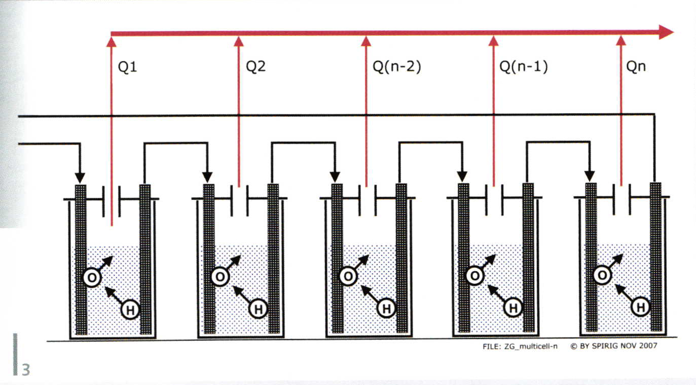
Basic laws of physics cannot be eliminated, but with a certain technological skill could be circumvented. For example, take five electrolysis containers (fig. 3), wire them electrically in series and connect each gas outlet in parallel. This reduces the required electrolysis current for a 100 l/h rate to a fifth or 33 amperes for this 5- cell structure. The dc supply voltage increases by a factor of five (easily manageable) but the needed dc current decreases by a factor of five; accordingly, the current loss will fall by a factor of 5 x 5 = 25. This solution is reasonable, but it is mechanical complex, not a practical solution.
A considerably more sophisticated and practical solution is found in a sandwich-like arrangement of the electrodes as seen in the center of the gas generator (fig. a). This technology has been consistently refined and is protected by a series of patents issued since the first patent granted about 25 years ago to the Swiss firm Spirig. The actual cell stack there holds 22 cells operated up to a maximum current of 19 amp which corresponds to a mono-cell structure of 22 x 19 = 418 Amps or to a max gas rate of 418:165 = 253 l/h. The 418 A(1-cell) is 22-times higher than the 19 A(22-cell). The heat losses created in the mono-cell would therefore be 22 x 22 = 484-times higher when compared to the 22-cell design.
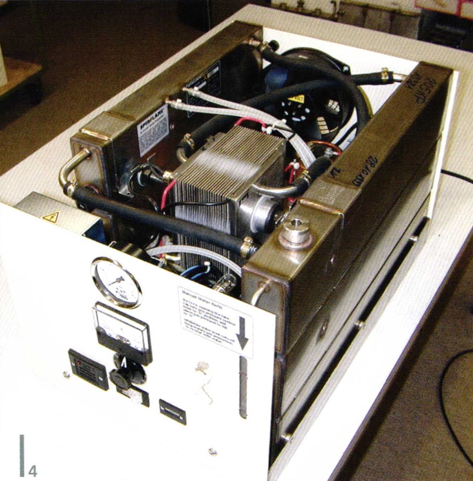
The latest generation of this electrolysis technology is the gas generator known as Spirflame® model Karat250® (fig. 4) intended for goldsmith work. This Karat250® can permanently deliver a maximum of 250 liters of gas per hour. The also patented multiple fluid storage tanks contain the permanently residing electrolyte fluid and the water added for consumption. A maintenance-free electric driven, magnetic coupled rotary pump feeds the multi-cell block with the electrolyte + water fluid mixture. A thermostatic controlled fan minimizes noise. The fluid level in tank is visible in a LED backlit level gage. In the event of a malfunctions, the Spirflame® automatically disconnects and locks-out the 230 vac mains supply. To re-activate the gas production a manual reset will be needed.
by Ernest Spirig
Related Articles
Gloves and the Jeweler

Channel Setting Tools Designed For Wax
How to Modify Wooden Ring Clamps

How to Modify Separating Tweezers


The All-In-One Jewelry Making Solution At Your Fingertips
When you join the Ganoksin community, you get the tools you need to take your work to the next level.
