Stone Setting Techniques
Article: Cluster Ring Assembly
One of the most difficult types of construction in jewelry is assembling a cluster of settings supported by a wire cage or basket. In this project, a marquis shaped center stone is surrounded by twenty two diamond melee with a total weight of 1 carat.
The assembly is complicated because the stones are different sizes and mounted at different levels in the ring. The outside dimension of each setting matches that of its stone, so that when viewed from the top, only the stones and the tips of the prongs are visible.
This ring is suggested only for those with extensive experience in goldsmithing, as it is constructed from over sixty pieces of metal. The problem of holding so many pieces in their exact position is overcome by using an investment mold to hold the components during soldering. This project requires many precision skills such as measuring, making tubing, sawing, filing, bending, forming, and an elaborate method of setting up and soldering the elements together.
1.
The first task of this project is selecting stones of the correct sizes. This project requires stones of specific sizes so that they will fit together closely without overlapping (Figure P30-1). The design calls for a marquis center stone measuring 4 mm by 8 mm, two 7-point stones with a diameter of 2.7 mm, six 5-point stones with a diameter of 2.4 mm, and fourteen 4-point stones with a diameter of 2.2 mm. The total weight of the diamonds should be approximately 1 carat.
 |
| P30-1 - Layout of stones by size |
2.
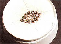
Place a small amount of plasticene (modeling clay) in a symmetrical domed mound on a flat surface. In the center, lay out a cross. Now place all of the stones in position, following the layout diagram in Figure P30-2. Take time to do a good Job, because the entire project is dependent on the proper arrangement of the stones. Too much space or too little space between the stones will cause serious problems later.
 |
| P30-2 - Stones arranged on clay |
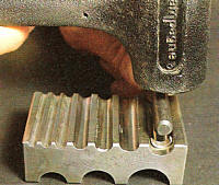
3.
The center stone is a marquis measuring 8 mm by 4 mm. The simplest way to make the setting is to form two crescent shaped strips and solder them together. The two strips are 1 mm thick, 2.5 mm wide, and 11 mm long. Shape the strips in a swage block, by selecting the groove and punch with a contour to match the girdle of the marquis (Figure P30-3).
 |
| P30-3 - Forming the marquis setting in a swage block |
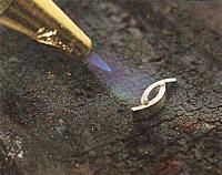
4.
File one end of each crescent to meet the other when fitted together at the correct size. Place them in position on a charcoal block. Use hard solder to solder together the two halves of the setting (Figure P30-4). Quench, pickle, rinse, dry, and clean. Remove excess metal from both ends, by sawing and then filing.
 |
| P30-4 - Soldering the marquis setting |
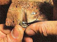
5.
Use a saw or flat graver to carve a seat on the inside of the setting. If using a graver, place the setting into dopping wax or shellac that has been melted onto the top of a dowel (Figure P30-5). The seat must match the contour of the pavilion of the stone. Use a pair of dividers to locate and lightly scribe a vertical line at the midpoint on both sides of the setting. This reference point will aid during the layout for soldering.
 |
| P30-5 - Using a graver to carve a seat in the marquis setting while mounted on a dop stick |
6.
All the settings for the round stones are made from one piece of tubing, even though the settings are different sizes. A piece of tubing is formed for the largest setting. After the required number of sections is cut off, the remainder of the tubing is pulled through a draw plate until the next size is reached. More sections are cut off, and then the tubing is drawn down even further until the smallest size sections can be cut off.
7.
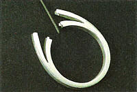
Calculate the width of the blank for the largest required tubing, 2.7 mm with a wall thickness of 0. 5 mm. The blank for the tubing should be 8 mm wide, 0. 5 mm thick, and 10 cm long, more than enough to provide all of the settings plus a tab of 15 turn. Draw the tubing to about 3 mm and then solder the seam with hard solder. The top unit of the ring, with all of the settings, is constructed exclusively with hard solder. The advantage of limiting work to hard solder is that any subsequent assembly or repair can be made with medium solder. Clean and then draw the tubing until it reaches the desired size of 2.7 mm.
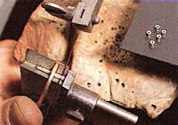
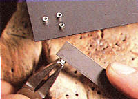
8.
All of the settings for this ring have the same outside dimensions as their corresponding stones. Each of the tube sections should be 1.9 mm tall, so set the end stop of the tube cutting jig at 1.9 mm. Cut off tubing for the required two settings, plus a few extra sections of each size, as insurance if some are lost or ruined. The cost in time and materials for making extra sections now is far cheaper than running short and having to begin the process again (Figure P30-6). Draw the tubing down to the next size, 2.4 mm, and cut off at least seven sections. Reduce the tubing to 2.2 rum, and cut off at least fifteen sections. Check all sections for the correct measurements, with the top and bottom flat and parallel. Use a scraper to remove burrs on the inside, and a needle file to remove burrs on the outside.
 |
| P30-6 - Cutting off tube sections |
9.
Two 2.7 mm four-prong settings are needed for the two 7-point diamonds at the ends of the marquis. Make these settings with four 0.8 mm prongs attached to each tube section, while all the other settings are constructed without prongs, which are attached at the end of the assembly process. Locate the seams on each of the 2.7 mm sections. Use a saw blade to groove the tubing at the seam, as well as at the three other points located 900 apart, around the tube. With a 0.8 mm round-edge joint file, deepen the grooves to a depth of about 0.4 mm so that the prongs will sit halfway into the tubing (Figure P30-7). Special draw plates that notch the tubing to accommodate prongs may be ordered especially for this purpose.
 |
| P30-7 - Notching the tube sections with a round edge joint file |
10.
Draw down enough wire to produce about 40 cm of 0.8 mm round wire for the prongs. Bend two 50 mm long sections into U shapes. Each should have a gap of approximately 1.9 mm so that the notched sections fit into the open U. Set up the two notched tube sections between the two U-shaped pieces of prong wire, leaving approximately 4 mm between the tubes (Figure P30-8).
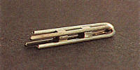 |
| P30-8 - Assembling U-shaped wires and tubes to make two four-prong settings |
11.
Solder the tubing sections in place, with one prong wire soldered into each of the notches, including one that is on the seam. Clean and cut off the settings, leaving at least 3 mm on top for the prongs and a small excess at the bottom (Figure P30-9).
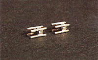 |
| P30-9 - Two four-prong settings |
12.
Now that all of the settings for the ring have been made, the next step is to set up for the first stage of assembly. Place a mound of clay on a hard nonporous surface such as metal or plastic. All of the settings will be positioned on the clay as they are to be soldered (Figure P30-10). The marquis is the main attraction of the ring and sits on a higher level than do the smaller round diamonds. Follow the diagram for the position and relative heights of the settings, in comparison with the height of the marquis.
 |
| P30-10 - Diagram of setting heights |
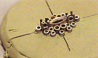
13.
Carefully inscribe the clay with a cross as a reference for the placement of the settings. Place the marquis setting precisely in the center of the cross. Use the midpoint lines on the marquis setting to help line it up properly on the cross. Add the two four-prong settings at the ends of the marquis, with the top of each tube portion 1 mm below the top of the marquis setting.
14.
Add the other eight tube sections of the inner row, as indicated by the layouts. If not all of the settings fit, with each touching the marquis, extra space will be needed. It may be gained by filing notches on the prongs of the 2.7 mm settings, facing the marquis and from a point I mm below the top of the tube section. In this way, the two adjoining settings can get closer and actually touch the tube section of the larger 2.7 mm prong settings. As each tube section is added, place its seam in contact with the marquis setting. Check repeatedly for vertical alignment, position, and height, adjusting as needed (Figure P30-11). Double check all views of the assembly for absolute precision. Remove the floor of a paper cup and place the cup around the clay mound, forming a dam to hold the investment. Note that the components of a complex assembly such as this are usually polished before they are soldered together. The polished surfaces are protected from oxidation by being coated with a boric acid/alcohol mixture.
 |
| P30-11 - Marquis and inner row of settings set up in clay |
15.
Mix a small portion of investment in a container, adding water until the solution is thick and creamy. Stir the mixture thoroughly for one minute. Very slowly pour the investment over the pieces, building up a mound that completely covers the assembly (Figure P30-12). In a few minutes, after the investment has completely dried and hardened, turn it over and carefully remove the clay with a pointed tool. Try not to dislodge any of the pieces. If an element moves out of place, it can usually be placed back into the investment mold. Any residual clay will oxidize upon heating and prevent the solder from flowing. For that reason it is important to remove all of the clay. Use a steamer to blast the exposed portion of the assembly, removing the last traces of clay. The underside of the assembly should now be exposed and ready for soldering.
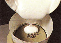 |
| P30-12 - Pouring investment over the assembly |
16.
Flux the contact points and add small snippets of hard solder, touching both sides of every joint (Figure P30-13). Heat the entire assembly evenly with a neutral flame, and solder the elements together. Use a pick to add small amounts of solder as needed. The underside or backside of a piece of jewelry should be just as neat and attractive as the front is. When soldering is complete, quench and break away the plaster. Use a steamer to loosen reluctant investment from the assembly. Remove flux and oxides in a pickle pot. Check for the correct position of all elements and adjust as needed.
 |
| P30-13 - Exposed underside of inner row of settings set up with solder while embedded in investment |
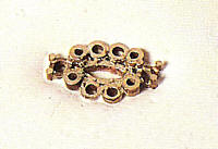
17.
Lay out a cross on a new mound of clay. Replace the assembly on the cross, and position the remaining outer row of settings by referring to the diagrams (Figure P30-14).
 |
| P30-14 - Soldered inner assembly with outer settings set up in clay |
18.
Repeat Steps 15 and 16 as the outer row of settings is soldered to the assembly (Figure P30-15).
 |
| P30-15 - Underside of inner row and outer row of settings embedded in investment and set up with solder |
19.
Now that the settings have been assembled, it is time to add the remaining interior prongs (Figure P30-16). Referring to the diagram, drill holes between the settings at the points indicated for each prong. Do not add the prongs around the outside of the assembly at this time. Use a 0.7 mm bit to drill from the top, the locations for the prongs around the marquis. If needed, you can use a 0.7 mm long tapered bur to notch the sides of the marquis setting to accommodate the prongs. After drilling, steam the assembly so that foreign matter such as oil or wax from the drill bit is removed.
 |
| P30-16 - Diagram of prong locations |
20.
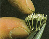
Cut off the fourteen 8 mm prongs from the same 0.8 mm wire that was used earlier for the U elements. Place each prong in a pin vise and file a long taper on one end. Because the prongs are 0.8 mm and the holes are 0.7 mm, this is necessary to insert them. The undersized hole and tapered prongs require that the prongs be forced into position from the top. About 0.5 mm of each prong should protrude from the bottom of the assembly, to be removed later. Set up the entire assembly in clay, with the top upward. Cover with investment and allow to dry. Next, remove the clay, revealing the bottom, and solder all of the prongs in position. Again, do not use excessive amounts of solder.
21.
Finally, the outer prongs and wire cage are added. Use the 0.8 mm round edge joint file to notch the midpoint on the outside of each of the twelve outer settings, and then set the assembly right side up into a tall mound of clay. Cut off twelve 14 mm lengths of prong wire. Place them in the grooves in the outer set rings and push them deep into the clay until only 1.5 mm of wire protrudes above the top of each setting. The rest of the wire, which will become part of the wire cage, should stick into the clay. Cover the assembly with investment and repeat Steps 15 and 16, soldering the outer prongs to complete the top assembly (Figure P30-17).
Another method for soldering the outer prongs is to hold the assembly in a third hand. Flux and sweat some solder onto each prong while holding in a pair of solder tweezers. Then solder each of the prongs into position one at a time.
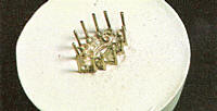 |
| P30-17 - Exposed underside of assembly with outer prongs set up for soldering |
22.
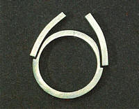
With the body of the ring complete, it is time to make the underbezel, which will rest on the finger and support the wire cage. The underbezel is made from 1 mm square wire that is bent into a 6-by-12 mm oval. Starting with annealed wire, use a pair of round-nose pliers to bend one end into a semicircle with an outside diameter of 6 mm. Form the wire around the pliers again, creating the other end of the loop 12 mm away, while leaving an overlapped section of wire (Figure P30-18). Saw a straight line across the overlapped ends of the wire, and use hard solder to join the ends.
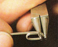 |
| P30-18 - Bending the underbezel |
23.
Select a groove in the swage block that matches the diameter of a size 6 ring. Place the underbezel into the groove lengthwise. Select the shaft of a ball punch that matches the ring size. Place the shaft on the underbezel and strike it with a bounceless mallet, forcing the underbezel into the die (Figure P30-19).
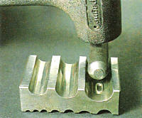 |
| P30-19. Forming the underbezel |
24.
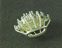
The next step is to bend the long ends of the outer prong wires into a basket or cage to meet the underbezel. Use a pair of chain nose pliers to bend the two wires on the opposite ends first. Grab them near the top and bend them inward to meet the underbezel 4 mm below the assembly (Figure P30-20). Continue to bend all the wires by working in opposite pairs. Work systematically and symmetrically, to ensure precision and uniformity. Bend the wires with even spacing between them. Clip the the wires to meet the underbezel at the required 4 mm distance. Keep checking and adjusting until all of the wires meet the underbezel evenly and uniformly. File the ends of each wire square.
 |
| P30-20. Bending the basket wires with chain nose pliers |
25.
Use binding wire to hold the cage and the underbezel in position, as all the wires are soldered at the same time (Figure P30-21). Up to this point only hard solder should have been used on the entire assembly.
 |
| P30-21. Basket wires soldered to the underbezel |
26.
There are many possible shank designs that will complete the ring. One traditional method is to make a band of metal with two struts bridging upward to the assembly. For a size 6 ring, start with a 57.8 mm section of 2 mm square wire. Form the shank around a ring mandrel; solder the ends; and then round it on the mandrel. From the same 2 mm square wire, cut off two sections, each 16 mm long.
Form them in a groove with a greater diameter than the ring shank. The curve should enable the struts to smoothly bridge the distance between the shank and the tops of the side wires. Place the shank flat on a bench, and with the seam in the shank upward, place the struts over the shank. Scribe the outlines of the struts onto the shank. Pierce and file the shank to accommodate the two struts (Figure P30-22). The components must fit precisely to ensure complete soldering. Solder together the shank and struts with hard solder. After soldering, file and sand the sides. Use a file to modify the struts so that there is a smooth and even transition to the shank.
 |
| P30-22. Shank with cutouts for side struts |
27.
With the shank assembly resting on a ring mandrel, place the top assembly next to it. Try to line up and center the elements visually, and scribe a line on each of the struts where the top assembly will fit. Scribe two lines on the shank, showing where to cut it apart. Better safe than sorry, so be conservative in determining how much metal to remove. More can always be filed away later. However, if too much is removed at the start, the shank assembly will have to be discarded. File the four ends of the shank assembly flat and at the appropriate angles to meet the top assembly at the four designated points. File a notch into each shank end to accommodate the juncture of the underbezel and the side basket wires. Use an 0.8 mm cylinder file to groove the four ends to meet the side wires (Figure P30-23). Work symmetrically and methodically, checking and adjusting as needed so that the shank will snap in place, with enough tension to keep it from moving.
 |
| P30-23. Using a cylinder file to file the shank ends to meet the basket |
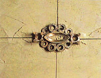
28.
The final step in constructing the cluster ring is to solder together the two assemblies. Snap the shank and struts onto the top assembly and solder the four joints with medium solder. Finish the ring as desired (Figure P30-24).
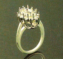 |
| P30-24. Finished cluster ring |

The All-In-One Jewelry Making Solution At Your Fingertips
When you join the Ganoksin community, you get the tools you need to take your work to the next level.
