
Causes & Prevention of Defects in Wrought Alloys
Much of the recent literature on defects that occur in jewellery manufacture is focused on those occurring in lost wax investment casting. However, defects can also occur during casting of ingot and its fabrication into sheet, tube, wire and rod as well as their onward fabrication into jewellery components by processes such as stamping and forging. These defects, along with their causes and prevention, are briefly reviewed in this article, although those defects occurring in the die-striking of findings are described elsewhere in this issue.
10 Minute Read
This article "Causes & Prevention of Defects in Wrought Alloys" cites the numerous causes of defects in wrought alloys and how to prevent them from happening.
Introduction
Much of the recent literature on defects that occur in jewellery manufacture is focused on those occurring in lost wax (investment) casting, for example reference (1). However, defects can also occur during casting of ingot and its fabrication into sheet, tube, wire and rod as well as their onward fabrication into jewellery components by processes such as stamping and forging. These defects, along with their causes and prevention, are briefly reviewed in this article, although those defects occurring in the die-striking of findings are described elsewhere in this issue (2). Examples of many defects can be found in the Handbook of Casting and Other Defects (1), and are referenced in the text where appropriate.
Defects Arising from the Cast Ingot or Continuously Cast Stock
Piping and Shrinkage Porosity
A pipe is the funnel-like depression at the top of a cast ingot that results from shrinkage during solidification. When the ingot is subsequently worked (forged and/or rolled), this will give a centre- line defect along sheet, strip or wire, particularly if the pipe surface is oxidised. This can lead to a splitting apart of strip and sheet during subsequent rolling, a defect known as 'alligatoring', Figure 1. An example of delamination due to a pipe is given in the Handbook of Casting and Other Defects (1), Case 16 on page 47.
The region containing the pipe should be cropped off before working and recycled as scrap of known quality. Internal shrinkage porosity should weld up and disappear provided the inner surfaces are clean and free from oxide.
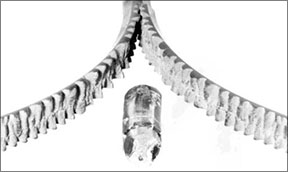 |
| Figure 1 Example of 'Alligatoring' (splitting) of a gold alloy rod during first rolling pass (courtesy Engelherd-CLAL, U.K.). This hard alloy is known to be difficult to fabricate. |
Blistering
Blistering on the surface of sheet and strip may be caused by gas porosity trapped in the cast stock or arising from reactions with the atmosphere during annealing treatments. An example of blistering and internal porosity in 18 ct yellow gold due to the 'steam' reaction during annealing is given in reference (1), Case 26 on page 67.
The problem can be avoided by control of casting or annealing conditions, including factors such as the dissolved gas or base
metal oxide content in feedstock materials through good de- oxidation procedures in melting, annealing temperature and avoiding the use of hydrogen-rich annealing atmospheres.
Inclusions
Inclusions in the cast stock are insoluble particles such as oxides and silicides. These can lead to problems of cracking during
working or to the formation of hard spots that can affect the quality of final polished surfaces ('comet tail' effect). Inclusions may be pieces of crucible or furnace lining which have fallen into the metal or they may be formed by chemical reaction, e.g. between absorbed gas and an alloy constituent. Regular inspection of crucibles and furnace linings, cleanliness of working surroundings and a consideration of possible reactions is important if inclusions are to be kept to a minimum. Many examples of defects due to inclusions are given in reference (1).
Contamination
Contamination of the melt may cause embrittlement and catastrophic cracking during working. The most notable example is the presence of very small amounts of lead that usually has been accidentally introduced as soft solder traces in recycled scrap. Other embrittling contaminants include silicon, sulphur and other low melting metals such as bismuth. Do not recycle scrap of unknown quality; such scrap should be analysed and checked for such impurities. Many examples of defects due to contamination of the alloy are given in reference (1).
Surface Quality
Surface quality of the final product may depend on the surface quality of the initial cast stock. Remove surface oxide by acid pickling prior to working since it is more difficult (and costly) to remove the oxide after it has been ground into the surface of sheet or rod. Excessive amounts of a mould dressing such as machine oil or trapped flux can give large depressions in the ingot surface. A thin continuous film of oil applied to the mould wall is recommended and excess flux should be removed before pouring the melt.
Splashes, slivers and spills are caused by molten metal splashing on the mould wall and solidifying with an oxide surface before being covered as the melt fills the mould. These can separate and peel away at the oxide interface during working, resulting in an uneven surface. Inspect ingot surfaces so that they can be trimmed and filed, where necessary, to smooth out depressions, remove splashes and spills, and gouge out particles embedded into the surface
Defects Arising as a Result of the Working Process
Rolling of flat products - sheet, strip and foil
Finishing rolling
Poor surface quality can arise from use of poor quality rolls with scratched or damaged surfaces. Finishing rolling should be done using small diameter rolls with highly polished or chromium plated surfaces to achieve a mirror-bright finish. Roll surfaces should be continuously wiped to keep dust and other particles from scoring or marking the rolls or being rolled into the strip surface. Cover the rolling mill when not in use to protect roll surfaces
Roll misalignment
Misalignment of the rolls leads either to curvature of the strip to one side as it comes out of the roll gap, if it is relatively thick, or to a wavy edge on one side if it is thin strip, Figure 2. Adjust the roll screws to give a parallel roll gap.
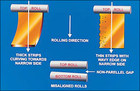 |
| Figure 2 - Defects due to misalignment of the rolls |
Roll bending
Roll bending under the action of the rolling force required to reduce strip thickness can lead to uneven thickness across the width of the strip or to wavy edges on both sides of the strip, Figure 3. Either decrease the reduction per pass, together with more frequent interstage annealing, to reduce the rolling force or, preferably, use a four-high rolling mill where small diameter work rolls are backed by larger rolls to prevent the work rolls bending under load, Figure 4.
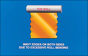 |
| Figure 3 - Defects due to roll bending |
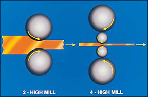 |
| Figure 4 - Minimising roll bending using a 4 high mill |
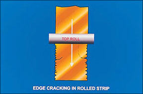
Edge cracking
Edge cracking is commonly caused by overworking between anneals. It is important to trim edges at the time it occurs as further rolling will increase the danger of some cracks suddenly running into the centre of the strip and turning through right angles, greatly increasing the amount which has to be scrapped, Figure 5.
 |
| Figure 5 - Edge cracking |
Gauge (thickness) control
Modern large mills usually have sophisticated automatic gauge control systems but for the jewellery manufacturer this may not be possible. Care should be taken to ensure uniform thickness along the strip length and across its width. Variations in thickness will give variations in forces required in subsequent sheet metal forming operations and this may lead to higher reject rates and risk of increased tool wear and breakage. If strip is sold to a specified minimum thickness, any additional thickness over specification has to be paid for by the strip manufacturer and for carat gold strip this will be expensive. Finish rolling with light reductions as sizing passes before final annealing will help to control gauge.
Rod rolling
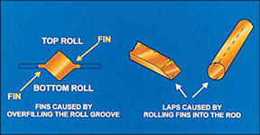
Fins and laps
Fins are caused by trying to push too much metal into the rolling groove, i.e. attempting too large a reduction, so that the rolls are forced apart and the excess metal is squeezed out sideways, Figure 6. If the fins are subsequently rolled into the rod, they become laps that form planes of weakness and they can open up at later stages, particularly under torsion or a twisting motion.
Such defects can be prevented by avoiding excessively large reductions and by rotating the rod through 90. between each successive pass.
 |
| Figure 6 - Formation of fins and laps |
Drawing
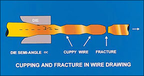
Cuppy wire
The most common defect in drawing is breakage or necking down as the wire emerges from the die, Figure 7. There are four possible causes.
- a) The wire is overworked and requires annealing.
- b) The presence of inclusions can give rise to weak spots in the wire.
- c) Too large a reduction per draw is being attempted. For large diameter wires, the reduction may be 25-45% depending on the workability of the particular alloy but, as the diameter is decreased, the reductions may be down to 15-20%.
- d) A breakdown in lubrication gives an increase in friction between the wire and die surfaces and this lowers the reduction that can be given.
 |
| Figure 7 - Cuppy wire |
Sheet metal forming
The occurrence of defects in sheet metal forming and their prevention is a complex subject. Fracture during forming will take place at the weakest or thinnest point in the part being formed. This is most likely to be where the sheet has been bent under tension round an angle, as extra thinning will occur there. There is a maximum or limiting size of blank that can be successfully formed without failure occurring at this point. It may be necessary to partly form in one punch-die set and then further form in other punch-die sets. The subject has been reviewed (3) and this should be published in the near future.
Orange peel effect
This is the formation of a rumpled surface on deformed sheet or wire, visible to the naked eye, and is due to a large grain size that results from over-annealing. An example is shown in Figure 11 of reference (2) on page 19 in this issue. Some 14 ct alloys are particularly prone to this effect. The formation of large grain sizes is sometimes compounded by annealing material with low amounts of deformation and/or by the presence of small additions such as silicon in the alloy (4). Orange peel may show up on chain link surfaces or on the surface of die stampings. The effect is minimised or prevented by control of working and annealing schedules such that coarse grain growth does not occur. High annealing temperatures, such as occur with torch annealing, and low amounts of deformation favour large grain sizes.
Stress corrosion cracking
This is failure by spontaneous cracking of jewellery, due to either internal residual stresses or stresses applied in service, in the presence of a corrosive atmosphere. This latter can include acid fumes or gaseous chlorides (e.g. from domestic cleaners and chlorinated swimming pools). An example in 14 ct nickel white gold is shown in Figures 5 & 6 in reference (5), page 28 in this issue. Fracture can occur in service (i.e. jewellery is being worn or stored), long after the jewellery has been manufactured and tends to prevail in low carat jewellery (8-14 carat).
It is important to emphasise that low carat jewellery, if left in the worked condition, will contain residual stresses and that this leads to an increased risk of stress corrosion cracking. Residual stresses can be removed or reduced in magnitude by a stress relief anneal, typically 30 minutes at 250.C. This reduces the risk of stress corrosion cracking. Stress relief should always be done after jewellery repair or re-sizing of rings.
Fire cracking in nickel white golds
Fire cracking is the sudden massive cracking of nickel-containing white golds during annealing, following cold working, and is caused by large internal stresses due to the metallurgy of these alloys. It occurs with fast cooling (water quenching) after annealing. However, slow cooling in air can lead to phase separation and colour changes. Often, it can be alleviated by an intermediate rate of cooling such as placing the item on an iron plate to cool or forced air cooling. The topic has been discussed by Rapson (6) and reviewed more recently by Normandeau (7) - see reference (5) in this issue, where an example of fire cracking is shown in Figure 7 on page 28.
Cracking due to alloy embrittlement by impurities
This has been briefly discussed under the section on Contamination above. Small amounts of impurities such as lead and silicon segregate to grain boundaries and form low melting point phases. Ott has reviewed this problem in reference (8). Some examples are shown in reference (1), Cases 17 and 18.
References:
- D. Ott, "Handbook of Casting and Other Defects in gold jewellery manufacture", publ. World Gold Council, 1997.
- F. Klotz and S. Grice, "Live and Let Die (Struck)", Gold Technology, No. 36, Winter 2002, p 16-22
- M.F. Grimwade, "Sheet metal forming operations", Proc. Santa Fe Symposium, 1992, Met-Chem Research Inc (awaiting publication)
- D. Ott, "Optimising carat gold alloys for the manufacturing process", Gold Technology, No. 34, Spring 2002, 37-44
- M.F. Grimwade, "The 16th Santa Fe Symposium on jewellery manufacturing technology", Gold Technology No. 36, Winter 2002, p 24-32
- W. Rapson & T. Groenewald, "Gold Usage", Academic press, 1978
- G. Normandeau, "Fire cracking in white gold jewelry materials", Proc Santa Fe Symposium, 2002, Met-Chem Research Inc, p429-450
- D. Ott, "The effect of small additions and impurities on properties of carat golds", Gold Technology No. 22, July 1997, p31-38
Related Articles

Metal Conversion Chart
Choosing the Right White Gold

Jonathan Bonner: Whimsy and Vision

The Contemporary American Custom Goldsmithing


The All-In-One Jewelry Making Solution At Your Fingertips
When you join the Ganoksin community, you get the tools you need to take your work to the next level.
