Live And Let Die (Struck)
In a manufacturing environment, there are numerous pitfalls and problems that will conspire to prevent successful completion of a job. Some of these problems may be complex and involve highly technical investigations, explanations and resolutions; however, many are basic, avoidable mistakes that are easily remedied.
19 Minute Read
In a manufacturing environment, there are numerous pitfalls and problems that will conspire to prevent successful completion of a job. Some of these problems may be complex and involve highly technical investigations, explanations and resolutions; however, many are basic, avoidable mistakes that are easily remedied.
The manufacturing jeweler often relies on conforming quality product purchased from a vendor; therefore, it is very important that the vendor gets it right first time. As a supplier of die struck findings, Hoover & Strong must ensure that all product shipped to customers meets the intended requirements. If this is not the case, the jeweler's job is more difficult, and in some cases impossible. At Hoover & Strong, we have a "catalogue" of documented problems and use this to train new co-workers to easily recognize defects as they occur. This enables resolution and prevention with the minimum time and fuss, ensuring an economic and speedy solution. A sample of this catalogue has been outlined in this article in the form of case studies. Whilst the answers and resolutions may appear obvious and simple, it is not uncommon for co-workers who have not received adequate training to continue making the same basic mistakes. The often simple root causes are not recognized and, with no preventative actions instigated, problems will reoccur.
Remember the golden rule: garbage in = garbage out.
The case studies have been divided into two major family groups - those that are "materials" related and those that are "process and operator" related. Although the examples cited are from a die striking environment, they will apply to all areas of jewelry manufacture. There are numerous investment cast findings available and defect analysis of these is, in itself, a complete subject; much on this has been published on numerous previous occasions and so it will not be included in this article.
Materials related defects
The majority of material defects encountered when manufacturing die struck findings are relatively easy to identify and often just as easy to prevent and cure. Die struck findings are manufactured from wrought products, typically sheet, wire or tube. It has been assumed the composition and integrity of the cast billets conform to requirements, and so defects from these areas have not been included. This being the case, there are few major defect areas: mechanical properties defects, cold working defects and annealing defects. At least one example of each will be outlined in the case studies below.
Materials defect - Case 1: Cold working defect
Figure 1 shows an example of a typical defect encountered in die striking. The component, a solitaire shank, appears to be "laminated" or the metal has "picked-up" at one end. To manufacture this item, wire of suitable dimensions is placed into a die set and a drop stamp used to form the basic shape. The shank may go through several stamping operations before the excess material is removed and it is formed into the required "ring" shape. Up until the final bending operation, all of the stamping operations involve primarily compressive forces and allow little opportunity for any rolled-in surface defect to become evident. It is only when the shank is rounded into shape that the lamination becomes recognizable. The defect originates from the cold working operations used to produce the wire.
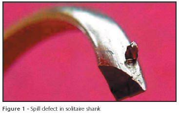
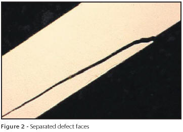
A static or continuous cast billet must have a smooth, high quality surface finish prior to any cold working operation to achieve the optimum surface quality on the finished product. Failure to do this can result in surface defects, known as "spill", being "rolled-over" or "rolled-in" to the surface. They remain hidden due to the nature of the deformation forces when producing wire or sheet, defects such as these rarely "weld" together during cold work. Other similar defects, known as "laps", can also occur during the wire drawing process. These are similar in nature but generally originate from intermediate processing, such as folded corners when squaring wire during the breakdown process. These defects only become evident during a subsequent manufacturing operation, such as the production of this solitaire shank. Here the outer face of the shank is subjected to tensile forces, pulling the two faces of the defect apart, Figure 2.
Although in-process inspection during wire manufacture can, on occasion, identify these defects, they are often difficult to identify until it is too late. The best remedy is prevention, ensuring best manufacturing practice is observed during production of the wire.
Materials defect - Case 2: Mechanical properties defect
For many operations during the manufacture of die struck findings, the most critical mechanical properties are the hardness and ductility of the mill stock material. Hardness is the measurement by which we specify the required temper; however, the ductility of the alloy is the key property. For example, an 18kt nickel white alloy has an annealed hardness of 220HV and can be deformed or cold worked; its structure, being annealed, is recrystallized and relatively ductile. A 14kt yellow alloy in the hard rolled condition also has a hardness value of 220HV but no ductility; its structure will not allow it. So we have different alloy compositions, same hardness values, but totally different ductility properties; the hardness is important in the context of each individual alloy. Generally, it is more useful to specify mill stock requirements in terms of the amount of cold work performed i.e. annealed, 10%, 20%, 50% etc. Depending on the purpose, the die struck findings manufacturer may require material to be in any one of these conditions.
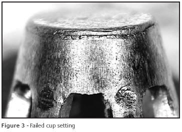
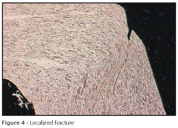
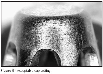
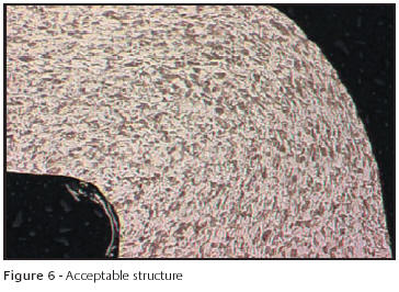
Ductility is critical when deep drawing findings components. Hoover & Strong manufacture a range of cup settings that are stamped as a one-piece item from rolled sheet. A suitable shape is flat blanked and then inserted into a tool set. It then undergoes several deep drawing operations to form the finished component. If the sheet supplied does not have maximum ductility for any reason, failure will occur at the base of the setting, Figure 3. Microsectional examination reveals the structure of the stamped sheet does not exhibit recrystallization, suggesting the stamped sheet was in the cold worked and not annealed condition, Figure 4. Fracture has occurred where the wall of the setting shows excessive local deformation, far greater than in the remainder of the section. Where correct temper mill stock is used, even flow can be seen in the base area due to a fully recrystallized structure being present prior to deep drawing, Figures 5 & 6. The correct resolution to this problem is to ensure the mill stock conforms to specifications before starting the job.
Materials defect - Case 3: Mechanical properties defect
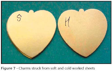
When die striking, it is not always advantageous to have mill stock in the annealed condition, particularly when a blanking operation is involved. To get a crisp, burr-free cut edge, strip is best cold worked to a certain degree for the optimum results. If the strip is too soft, a burr can be created by excess metal movement into the clearance gap between punch and die. Poor edge retention is also a common problem, as demonstrated in this example of a die struck charm, Figure 7. The edges are clearly "beveled" as a direct result of the material being too soft.
Materials defect - Case 4: Annealing defect
There are numerous methods available to manufacture the many different styles of anniversary band. A typical route is to strike washers from sheet stock and to form these, via several press operations, into the blank required. The blanks are then machined into the chosen style, dimensions, weight etc. A critical requirement for this operation is that sheet stock is correctly annealed prior to any subsequent forming operation. Depending on the family of alloy used, composition may have an effect on post-annealing mechanical properties.
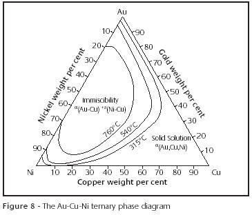
If bands are being manufactured from a general purpose yellow karat gold with negligible age hardenability, standard rolling and annealing techniques can be used to produce the mill stock. If, however, the composition of the alloy requires specific heating and/or cooling cycles, care must be taken. The example used here is of a blank stamped from a high nickel-containing 14kt white alloy. The metallurgy of nickel-white alloys is well documented and does not require re-iterating in this text (1-4). However, it is important to note that alloys containing high percentages of nickel, in particular 14kt and 18kt, undergo segregation. A solid state immiscibility field occurs in the Au-Ni binary system below 1510°F/821°C that influences the Au-Ni-Cu ternary relationship, particularly in the compositional ranges of commercially available 14kt nickel white alloys, Figure 8. As a result, the high nickel-containing alloys are intrinsically harder than standard yellow or low nickel-containing alloys and will work harden at higher rates.
This can result in two distinct problems. Firstly, due to the resultant higher intrinsic hardness values, if the alloy is slow cooled from annealing temperatures, the resultant component will be less ductile and unable to tolerate high degrees of cold work. This then influences the second problem. The tendency to cold work less between anneals for any given process is common. If insufficient work is performed prior to annealing, either during sheet rolling or blank formation, the resultant strain through the section will vary, typically being worked heavier at the surface and less in mid-section. Unequal grain sizes will result on annealing with the internal tensile stresses generated causing failure if cooled too rapidly - quench cracking (5). This cracking can be internal and may not be immediately apparent. Often it is only manifest as catastrophic failure on subsequent cold working. So maximum ductility will be achieved by quenching the alloy from the single phase region. However, the potential for quenchrelated failure is highest with this process. If we leave this alloy to slow cool, we will minimize the potential for cracking. However, the alloy will be in the least ductile state. What is required is a compromise annealing cycle that is calculated to give maximum ductility for maximum protection against failure.
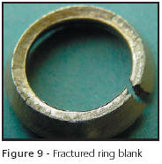
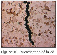
The ring blank in this case study has failed on sizing. Incorrect annealing and insufficient cold work during processing has resulted in the washer being less ductile, resulting in less tolerance to deformation. There is also some evidence of internal intergranular quench-related cracking present. It has withstood a minimal amount of deformation, but when stretched over one size has failed, Figure 9. Microsections confirm the failure mode, Figure 10.
The resolution to this problem is to stamp the washer from strip that has undergone sufficient cold work and then to apply the correct annealing cycle. This process will be a compromise but will give the optimum potential for success.
Materials defect - Case 5: Annealing defect
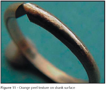
Some annealing defects may be the result of relatively simple problems. A component may have been annealed for too long or at an excessively high temperature, or a combination of both. This will generate excessive grain growth and result in an orange peel textured surface when deformed, which can be difficult (and sometimes impossible) to finish to an acceptable standard. Most cases of "over-annealing" are as simple as this, but in some cases further investigation is required to identify the root cause. Case study 5 again involves a solitaire shank. There is an orange peel surface texture becoming evident when formed into the final shape, Figure 11.
The alloy used for this component was an 18kt red, an alloy family that tends to generate relatively large recrystallized grain sizes after annealing. These alloys are also susceptible to a phenomenon known as "order-disorder" hardening (6). At certain Au/Cu ratios the intermetallic compounds Au3Cu, AuCu and AuCu3 will form below 410°C. Above this temperature, a complete range of solid solutions exists known as the "disordered" state, where atoms are randomly situated throughout the crystal lattice. If quenched from above this temperature after annealing, the resultant structure is relatively weak and therefore ductile.
For a typical 18kt red alloy composition, if slow cooled below this temperature, the intermetallic compound AuCu forms. Gold and copper atoms migrate to alternate layers, known as the "ordered" state, resulting in considerably more lattice strain than that generated when disordered. The resultant alloy is much harder and less ductile, tolerating less cold work before further annealing is required.
A phenomenon known as the "critical strain energy" must also be considered. In simplistic terms, this is the amount of strain energy required in a system - cold work - for recrystallization to occur. Once this level has been exceeded, the greater the amount of cold work done on a component, the smaller the resultant grain size will be after annealing. Minimal work will result in large and often irregular annealed grain sizes.
The solitaire shank in this case study has an excessively large grain size - measured at an average of 0.2mm. Investigations confirmed this was the result of insufficient cold work imparted into the component prior to annealing. As a result of an incorrect intermediate processing anneal - it was cooled too slowly resulting in a degree of ordering and therefore loss of ductility - only minimal deformation was possible between anneals. This was sufficient to cause recrystallization but with a resultant large grain size. Coupled with the fact that this alloy family tends to generate large grain sizes on annealing, we have the cause of the problem.
Resolution is, once again, to correctly process the mill stock prior to component formation, and to ensure all process specifications are rigidly applied. Given the correct in-process anneal, the component had sufficient ductility for enough cold work. An acceptable grain size was the result.
Materials defect - Case 6: Annealing defect
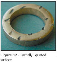
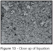
Always be aware of the obvious. This washer has undergone a pre-forming anneal and "did not appear right", Figure 12. It was immediately obvious that the component had been overheated during the annealing operation. Marks from the furnace belt can clearly be seen, along with partial liquation at the surface, Figure 13. Annealing furnaces must be periodically checked to ensure the control systems are within calibration. Process related problems.
In a typical precious metal die striking plant, several factors influence how a production run is done. The sales volume of each product dictates the efficiency and amount of operator intervention. While technology has given findings toolmakers a vast array of options for automated tooling as well as robotics, economics has often limited their use. These options are expensive and due to the many styles and sizes offered by die struck findings manufacturers they are not always cost effective to use. Within a given style, some sizes sell thousands of units each month, while others may only provide minimum sales. Those with marginal sales that are needed to fill out a line or family of parts will be produced with manual, multiple step tooling. Efficiencies can be gained here through quick set-up designs and fixtures. However, the more manual steps there are, the greater the chance for processing problems.
Process Defect - Case 1: Tool set up problem
Incorrect set up of tooling accounts for over 30% of tool failure and is easy to avoid if care is taken to follow a few simple rules. In Figure 14, a hook was formed at the end of a shank blank. The distance between the cut off blade and the block caused this defect. In this case the clearance is too great. As a result, the tool lost much of its shearing action and actually began to form the end of the wire before it cut off. The clearance required is governed by the formula, presented earlier in the Gold Technology article on stamping (7). When clearance is required, a shim or feeler gauge should be placed between the two tooling components and removed when tightened. Also, frequent checks of the set-up during operation will prevent changes from ruining a job.
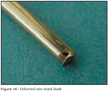
If the defective part in Figure 14 is cold forged, the result will be a seam forming into the surface of the metal that will not be visible to the naked eye. It will not be evident until the ring is rounded and then the seam will open up.
Process Defect - Case 2: Tool out of Adjustment
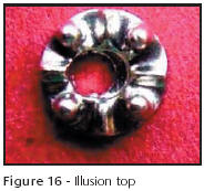
The illusion top shown in Figure 16 is a case of the gauge plate on a piercing tool being aligned incorrectly. In this case, the piercing of the illusion top is drastically off center. It chopped away part of the top itself on one side while leaving part of the background on the other. Rough handling or improper storage can result in tools being knocked out of alignment. All tools need to be tested upon set-up. A visual inspection needs to be performed prior to placing any tool in a machine. Misalignment and the need for polishing or sharpening will become apparent to the trained eye and can be resolved before the set-up begins.
Process Defect - Case 3: Snaking
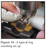
Shanks sometimes develop a twist in them, Figure 17, that's referred to as snaking. This is the result of rounding arbor-to-bending block misalignment. Figure 18 shows a common shank rounding set up. When the arbor is not square to the bending blocks groove, the forming will favor one side, resulting in the formation of a mild helix. When the ends of the shank are aligned by hand to attempt to correct this, the entire ring is distorted beyond repair as seen in Figure 17.
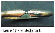
Proper tool set-up ensures that all components are level and square to each other and the machine. Snaking can also be the result of faulty tool making where the groove is machined crooked in the bending block or the block itself may be out of square. Also, it's not unusual for an arbor to bend or wear over time and this will cause these defects by pinching the shank harder on one side than the other.
The operator has tremendous influence on the outcome of every job. If he or she is careless, the results can be very costly. Parts can be ruined and expensive tooling damaged beyond repair. As in any manufacturing endeavor, thorough training is essential before allowing an operator to run any job. The quality of products can be only as good as the experience and dedication of the operator. The best practice is to train production workers to inspect their parts as they make them. Since they frequently handle these parts during each run, it takes negligible additional time to look at the quality of the findings as they work.
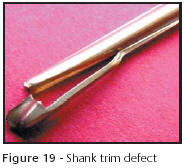
Process Defect - Case 4: Part placement error
Correct placement of pieces into stamping, trimming or piercing dies is essential to success. In the examples shown in Figures 19 and 20, the parts were not fully seated in the trimmers. This caused extreme damage to the findings and exposed the tools to excessive abuse. The part in Figure 19 was partially positioned in a trimming tool. The tool was damaged as a result of the punch and plate being driven out of alignment. An obvious defect such as this would never make it past the next step before being detected.
The illusion top in Figure 20 is normally run with thousands of identical parts. Like the shank in Figure 19, it too was partially placed into the trimmer plate but in this case, the tool was not damaged. It drops through a trim plate into a drawer filled with many other parts and can become difficult to separate from acceptable parts. A cup or container is usually placed in the machine bin to be emptied numerous times during such a run. This way, the defect may be discovered before it's buried among hundreds of similar parts.
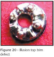
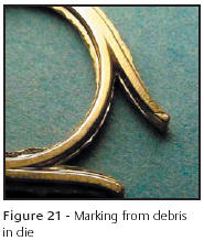
Figure 21 is a good example of a metal flake in a die marking the surface of a finding. In this case, a small piece of gold was resting on the bottom of the die when it was cold forged. The results can be seen in the form of an impression being made on the end of the prong. The operator failed to see the debris and continued to strike the parts resulting in most of them being marked in this manner. Die striking tools should be visually inspected after each strike and must be clean and free of any metal flakes or dirt.
Process Defect - Case 5: Tool Failure
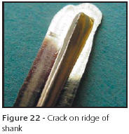
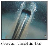
Three things can affect the usable life of tools and dies. These are damage, poor craftsmanship and wear. As said above, careless set-up and operator error can destroy the best tools. Poor craftsmanship can manifest itself in many ways. Flaws in steel or heat treatment can cause premature failure. The same can be said for choosing the wrong steel for a specific application. Cold forging dies require impact resistant steel such as S7 grade while using O2 steel for cup setting forming tooling is a good choice. However, if O2 steel is used for cold forging die blocks, the results will be less than acceptable tool life. Also, the design of a part can limit the life of a tool and this is illustrated in Figures 22 and 23. The sharp ridge along the top of the shank has caused the die to fail quicker than a more rounded design. In this case, the die has cracked along the ridge and in extreme cases, the die can split in half. The shank acts as a wedge and exerts great force within the cavity and can be very much like splitting wood if not properly annealed.
Process Defect - Case 6: Tool wear
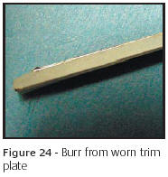
Wear is a fact of life with steel tooling. Routine maintenance such as sharpening will remove surface material, therefore reducing the life of the tool. Grinding the cutting surfaces of both the punch and plate sharpens trimmers as well as blanking and piercing tools. Parts are allowed to fall through these tools by the inclusion of a draft angle in the plate. They are narrower at the top than the bottom. If this were not so, the parts would stick in the die and stack up, destroying the tools. This angle will aid in ejecting the parts but it also governs the life of the tool. If the draft angle is too great, sharpening will open the impression and cause a ragged edge to form. This is called burring, where the space between the punch and plate is too great. Metal tears rather than shears as a result of this space. An example of burring can be seen in Figure 24. A burr has formed along the edge at the top of the part. Tumbling may remove light burring and, in some cases, realigning the tool may reduce it. Under no circumstances should a part like this be forged again. This would simply drive the excess metal into the part only to resurface later.
Conclusions
The case studies cited in this article are typical of defects occurring in the manufacture of die struck findings. The causes have been identified and their resolution to prevent their reoccurrence is shown to be straightforward. Many of these defects are preventable by improved operator training.
References
- G.P. O'Connor, "Improvement of 18ct White Gold Alloys", Gold Bulletin, 11(2), 1978, 35-39.
- G.P. O'Connor, "Alloy Additions for 18ct White Gold Alloys", Metals Technology, 6 July 1979.
- G. Normandeau, "White Gold's: A Review of Commercial Materials Characteristics and Alloy Design Alternatives", Gold Bulletin, 25(3), 1992, 94-103.
- S. Grice, "Failures in 14kt Nickel White Gold Tiffany Head Settings", Proceedings of The Santa Fe Symposium 2002, Met-Chem Research Inc, 2002, 189-230.
- M.R. Pinasco and E. Stagno," Deformation and Recrystalization of a Jewellery White Gold Alloy", Gold Bulletin, 12(2), 1979, 53-57.
- M.F. Grimwade, "Introduction to Precious Metals", Newnes Technical Books, 1985.
- F. Klotz, "Production of Gold Findings by Stamping", Gold Technology, No 33, Winter 2001, 13-16.
Related Articles

Hard 22 Carat Gold Alloy

Laser Welders Impacting the Jewelry Industry

Revolutionary PolishPlus Process

Full eBook: Doming Silver Beads


The All-In-One Jewelry Making Solution At Your Fingertips
When you join the Ganoksin community, you get the tools you need to take your work to the next level.