
How to Make a Tumbler
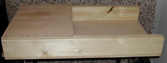
The construction process is simple enough if you have basic do-it-yourself skills. Firstly, assemble the timber frame as shown below using a length of 4x2 inch planed timber and a sheet of 1/2 inch plywood. In my case the base was 39 inches long by 16 inches wide. The plywood base was screwed to the bottom of the side members and then the top platform was screwed at one end.
2 Minute Read
The construction process is simple enough if you have basic do-it-yourself skills. Firstly, assemble the timber frame as shown below using a length of 4×2 inch planed timber and a sheet of 1/2 inch plywood. In my case the base was 39 inches long by 16 inches wide. The plywood base was screwed to the bottom of the side members and then the top platform was screwed at one end.
Below is the 20 mm self aligning plumbers block bearing used to support the tumbler shafts. Note the two grub screws for locking the shaft to the bearing and the brass grease nipple for lubrication purposes. These bearings can be obtained from specialist bearing supply companies.
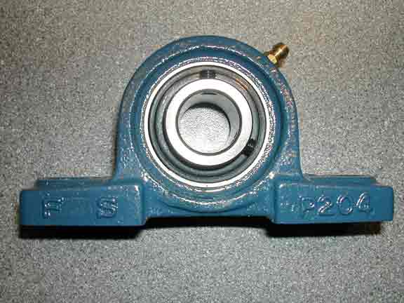
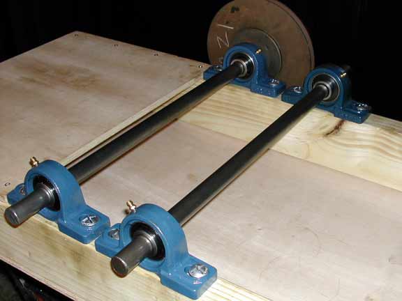
Position the components and drill locating holes for the bearings into the side members. The bearings can now be bolted in place or if you prefer, after painting. The 20mm shafts can be obtained from a welding shop.
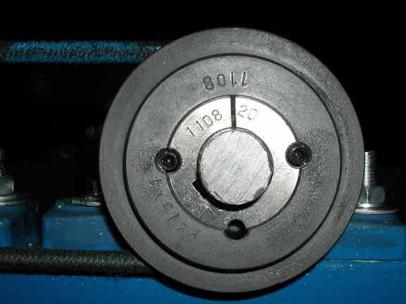
Below is a close-up of the taper-lock mechanism used with my pulleys. These are independent pulley hubs which can be changed according to the shaft size used. They lock the hub, shaft and pulley together. These pulleys were obtained from a specialist bearing company.
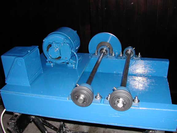
All pulleys were secured to the shaft ends and the tumbler was given a coating of protective paint. When dry, the electric motor with a speed of 1425 rpm was fitted along with a 2 inch pulley. The next pulley in line was 7 inches in diameter and fitted to the first 20mm shaft. On the opposite end of the shafts were fitted two, 3 inch pulleys One drove the second shaft at the same speed as the first. The square shaped box on the left of the photo houses the motor on/off buttons etc.
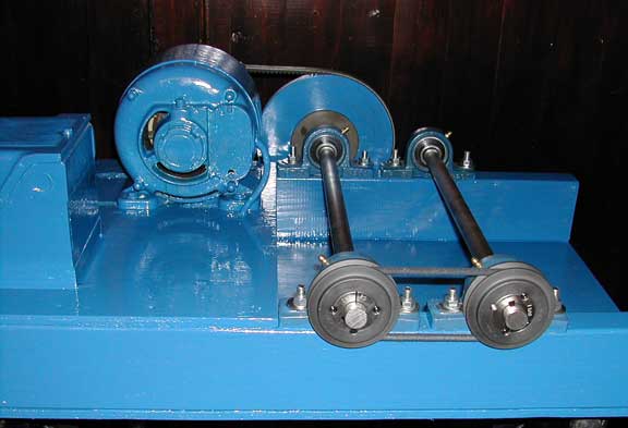
Rubber drive belts were fitted to the pulleys and the tumbler was given a final check before switching on. Placing a 61/4 inch barrel between the rollers produced a barrel speed of 56 rpm approximately. This speed can be varied by changing the barrel diameter used. A larger diameter barrel will reduce the barrel speed and a smaller barrel will increase it. For safety reasons, it is advisable to fit a guard around all pulleys.
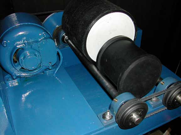
The photograph below show my choice of barrels. The smaller is a commercially produced 51/4 inch rubber barrel purchased from cooksongold.com and will be used for jewellery tumbling. The larger 71/2 inch diameter barrel was made by a friend using industrial plastic materials and will be used to tumble clock components.
Related Articles

Making a Multi-Grit Sanding Stick

Micro Vacuum Cleaner for Enamelists

Modified Setting Bur with Safe Edge Tool

Customized Solder Holder, Jet Sett, Blast Shield


The All-In-One Jewelry Making Solution At Your Fingertips
When you join the Ganoksin community, you get the tools you need to take your work to the next level.
