
How to Make a Wax Injector
You will require a 5 to 6 inch by 3 inch wide brass or copper tube, silver solder a cover on both ends a thicker one or double up for the base to retain the heat. Ideally the tube and top plate should be 1/8th inch thick with the base plate being.
5 Minute Read
To safeguard yourselves please follow these instructions carefully. A wax injector can be dangerous if not constructed and used correctly. These instructions are given freely and must only be used by those who are competent to undertake this work in a safe and proper manner. No responsibility will be accepted by the designer for accidents caused during manufacture or use of this injector.
You will require a 5 to 6 inch by 3 inch wide brass or copper tube, silver solder a cover on both ends a thicker one or double up for the base to retain the heat. Ideally the tube and top plate should be 1/8th inch thick with the base plate being ? inch thick approximately.
Drill a 3/4 inch hole in the top and silver solder a one inch brass internally threaded connector over the hole and in this connector fit a brass blanking cap with a rubber seal supplied by a plumbing store. This will serve as a supply point for the wax pellets and also a place where air pressure can be applied.
Drill the blanking cap to take a metal tyre valve and fit the valve into the end cap. DO NOT BE TEMPTED TO PRESSURISE THE VESSEL AT THIS STAGE. Next drill two holes either side of the central filler cap to take, on one side, a pressure gauge with its connector and on the other side a pressure relief valve with its connector. All connector can be obtained from a plumber's supply or DIY store.
Although I made my own pressure relief valve, I would recommend buying a professionally one for peace of mind. You will need a valve, which relieves pressure at 30 psi. Silver solder the pressure gauge connector and the connector for the relief valve into the top of the tank do not connect the relief valve or the pressure gauge just yet.
Next, drill a hole in the side of the tank at the front, one inch from the bottom to take a connector for the injector nozzle. This needs to be silver soldered in place. If you can purchase a commercially produced injector valve do so, but if you cannot I have included a sketch of the type I made for my own injector. A lathe will be required to do this work. As an update, it was found that an "O" ring works better than a tap washer to seal the injector delivery valve and by placing the spring outside, it allows room to fit a metal sealing cone between injector valve and tank body giving better sealing.
To heat the wax I've used a domestic hotplate with a thermostatic control. The thermostatic control is important to prevent overheating of the wax. Placing the injector tank in the centre of the hotplate helps prevent the wax solidifying in the injector nozzle.
Some way of measuring the wax temperature is required and I chose a digital clock/thermometer for this purpose. The type I bought had a wire with a sensor at the end, which allowed for the measurement of outdoor temperatures. These can be bought from a car accessory shop and I paid five pounds for mine. The range will need to measure as far as 80 degrees C. To use the temperature sensor you must first attach it with large nylon cable ties placed around the injector body so that the sensor is near the nozzle and in direct contact with the outside surface of the injector tank.
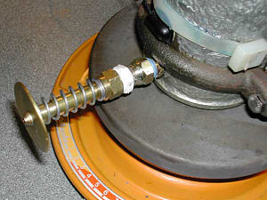
To secure the injector tank during use, I obtained a plumbers flange which fitted around the tank and then screwed it via a threaded bar securely to a wall. You will find these are standard plumbers fittings including the threaded bar. You should now be ready to fit and seal all components such as end cap with tyre valve, air pressure gauge, relief valve and injector valve.
To test the tank for leaks I used a tyre foot pump and pumped in air to a pressure of 5 psi. Then using a soapy water solution, I tested all joints for leaks and resealed as required using PTFE tape. When satisfied release the pressure and reapply air pressure to the injector tank taking it to 30psi (the relief valve setting)
I would recommend taking the tank to a tyre-fitting centre and asking them to do this for you in their safety cage. Once this has been completed and you are sure the relief valve has operated correctly you are ready to melt some wax and use the injector.
Firstly unscrew the end filler cap with tyre valve and fill 3/4 full with wax beads leave the top off and turn on the hotplate until the wax starts to melt, which takes around 15 minutes. When fully melted reduce to about half the temperature just to keep the wax molten. It will be obvious that by leaving the filler cap off you will be able to see the point at which the wax has melted. You will need to experiment with these setting to get the melt and simmer temperature correct. DO NOT OVERHEAT THE WAX. I have found that simmer temperature was about half the melt temperature.
Now you can screw the filler cap on tightly and re-seal. Using the tyre foot pump inflate the injector tank to about 10 (ten PSI) and maintain a wax temperature of around 65 degrees C. (sixty five degrees C) at this point you should be ready for injecting. It may be necessary to vary temperature and pressure under different conditions and best results will be found with practice.
If available a compressor can be used to pressurise the injector but only when there is a pressure delivery regulator and water trap fitted. Using a foot pump will produce about three or four waxes before having to pump again, which is usually about two strokes.
Please follow these instruction carefully. THEY ARE FOR YOUR OWN SAFETY.
 |
| Injector Nozzle Sketch |
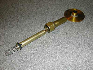 |
| Injector Nozzle Dismantled |
 |
| Plumbers Connector Used To Make Injector Valve |
 |
| An Alternative External Spring Arrangement for the Injector Valve |
Related Articles
Rules for Tools

Casting Tools and Products

Pollution Control / Metal Recovery

Restoring a Jewellers Vulcanising Press


The All-In-One Jewelry Making Solution At Your Fingertips
When you join the Ganoksin community, you get the tools you need to take your work to the next level.
