The Flex-Shaft System
The flex-shaft is a wonderful tool - but one that jewelers rarely use to its maximum advantage. Usually the first piece of serious equipment in which hobbyists or graduate jewelry students invest, the flex-shaft system makes bench work much easier: It reduces effort and fatigue, enhances production, and can be used for a variety of tasks, from scraping wafer-thin pieces of wax to grinding down larger pieces of metal for hollowware. Despite this, the tools accessories, power specifications, and range of uses have remained a mystery to many. This book is intended to solve that problem: It will attempt to demystify the flex-shaft system, and to educate each reader in how to use this essential tool to its full potential.
7 Minute Read
The flex-shaft is a wonderful tool - but one that jewelers rarely use to its maximum advantage. Usually the first piece of serious equipment in which hobbyists or graduate jewelry students invest, the flex-shaft system makes bench work much easier: It reduces effort and fatigue, enhances production, and can be used for a variety of tasks, from scraping wafer-thin pieces of wax to grinding down larger pieces of metal for hollowware.
Despite this, the tool's accessories, power specifications, and range of uses have remained a mystery to many. This book is intended to solve that problem: It will attempt to demystify the flex-shaft system, and to educate each reader in how to use this essential tool to its full potential.
A Brief History of the Flexible Shaft
The first flexible shaft was invented by the famous Scottish engineer James Hall Nasmyth (1808-1890), best known for his later development of the steam hammer. In 1829, Nasmyth (Figure 1-A) worked as an assistant to the then well-known British machine tool maker and inventor Henry Maudslay (1771- 1831). Years later, in a series of recollections, Nasmyth recounted his tool's development, reprinted here on page 10.
 A Mode of transmitting Rotary Motion by means of a Flexible Shaft,
formed of a Coiled Spiral Wire or Rod of Steel
"While assisting Mr. Maudslay in the execution of a special piece of machinery, in which it became necessary to have some holes drilled in rather inaccessible portions of the work in hand, and where the employment of the ordinary drill was impossible, it occurred to me that a flexible shaft, formed of a closely coiled spiral of steel wire, might enable us to transmit the requisite rotary motion to a drill attached to the end of this spiral shaft. Mr. Maudslay was much pleased with the notion, and I speedily put it in action by aclose-coiled spiral wire of about two feet in length.
"This was found to transmit the requisite rotary motion to the drill at the end of the spiral with perfect and faithful efficiency. The difficulty was got over, to Mr. Maudslay's great satisfaction.
"So far as I am aware, such a mode of transmitting rotary motion was new and original. The device was useful, and proved of essential service in other important applications. By a suitably close-coiled spiral steel wire I have conveyed rotary motion quite round an obstacle, such as is indicated in the annexed figure [Figure 1-B].
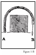
"It has acted with perfect faithfulness from the winch handle at A to the drill at B. Any ingenious mechanic will be able to appreciate the value of such a flexible shaft in many applications. Four years ago I saw the same arrangement in action at a dentist's operating room, when a drill was worked in the mouth of a patient to enable a decayed tooth to be stopped. It was said to be the last thing out in 'Yankee notions.' It was merely a replica of my flexible drill of 1829."
From this simple modification, the jeweler's flexible shaft was born. The modern flex-shaft can assist in many tasks, from drilling a hole to polishing metal to shaping wax. However, the myriad choices available in flex-shaft accessories - foot pedals, burs, abrasives, polishers, special attachments, specialty handpieces, and even the motor - can be daunting.
So what exactly is a flexible shaft? Actually, the term itself pertains only to one essential component of the whole system (the correct term is a "power rotary tool," but we will use "flexible shaft" or "flex-shaft" throughout the book). In total, the flex-shaft system consists of four components: the motor, the shaft itself, the handpiece, and the adjustable power source.
The Flex-Shaft Motor
In its essence, the flex-shaft motor has one goal: to rotate the flexible shaft. It does this through the magic of magnetism - or, in this case, the manipulation of electromagnetism. Break apart the motor shell (Figure 1-C) and you will find two magnetic components. The first, called the "field," is fixed to the motor case. The second, the "armature," is a rotating electromagnetic cylinder wound with copper, which is centered on and fixed to the end of the motor shaft.
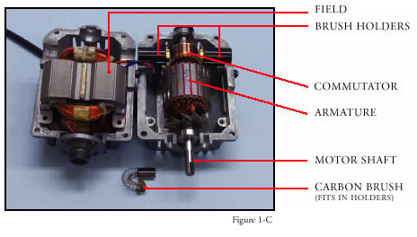
In the universal motor, the type most commonly found in flex-shafts, electrical current is introduced to the armature through the "commutator" (a cylinder comprising several insulated copper bars), which is mounted on the end of the armature. As current is applied, the armature is charged electromagnetically; the opposing polarities of the field and the armature interact - positive attracts negative, negative attracts positive - and the shaft begins to turn.
If the armature were allowed to turn without any further interference, eventually the polarities would align and the two magnets would repel each other. To offset that, the motor contains a set of carbon brushes that are mounted in holders on the inside of the case. As the armature rotates, the commutator's copper bars slide against the brushes, which reverses the direction of the current's electrons: positive becomes negative, and negative becomes positive. In this way, the polarities of the field and the armature are constantly alternating to ensure mutual attraction and continuous rotation, thus producing maximum motor torque.
The Flexible Shaft
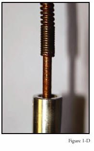
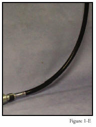
The shaft, approximately 1 meter (3.3 feet) in length, consists of a solid steel wire core surrounded by two sets of coiled wires (Figure 1-D). The inner coil is symmetrically wound in a tight configuration from one end to the other, while the outer coil, or silencer, is loosely wound with approximately 1 millimeter (0.04 inch) between each coiled segment. This coiled shaft then fits into a flexible rubber sheath (Figure 1-E). (The degree of flexibility depends on the system's manufacturer.)
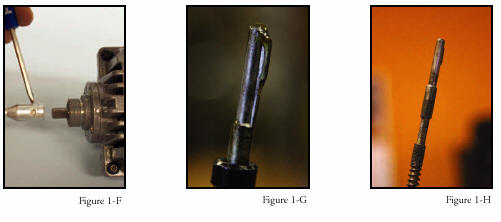
One end of the shaft has a thick-walled metal tube (motor coupling) that slips over the motor shaft and is secured by a setscrew (Figure 1-F). At the opposite end, the interior steel core wire extends past the coils about 2 centimeters (0.8 inch) and has attached to it a small piece of metal (Figure 1-G) that protrudes about 19 millimeters (0.76 inch) from the sheath tip (Figure 1-H). This metal tip acts as a "key" for the accurate mounting of various hand-pieces.
The Handpiece
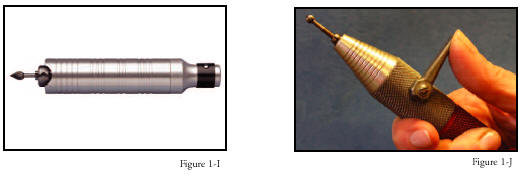
The flex-shaft handpiece (such as the popular Jacobs Chuck, Figure 1-I, or quick-release handpiece, Figure 1-J) can hold various accessories, from burs and drill bits to brushes and polishing wheels. The flex-shaft handpiece is attached to the sheath by a spring clip and catch ball mechanism. Detailed descriptions of handpieces are found in Chapter 3.
The Adjustable Power Source
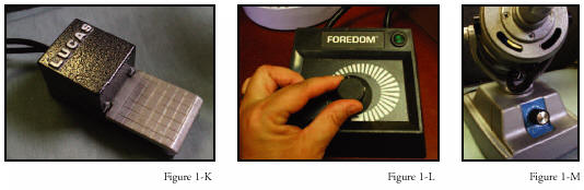
To contol the flex-shaft's power, jewelers have several options: a foot pedal (Figure 1-K), a bench-mounted dial control box (Figure 1-L), or a dial control in the base of the flex-shaft (Figure 1-M). The speed at which the flexible shaft rotates is varied by the amount of pressure placed on the foot pedal, or by positioning the dial at a particular setting.
Systems in the Industry
As with so many other areas of the jewelry industry, many of the accessories, handpieces, and power systems were derived from the expanding technical innovations in the dental industry. Indeed, several brands of flexible shafts, such as Pfingst, Buffalo Dental, and Foredom, were initially created specifically for the dental market.
Ultimately, goldsmiths discovered the advantages of the flex-shaft systems and began using them for polishing, detail work, and stone setting, among other repetitive applications. In the 1950s, artisan jewelers recognized the potential of the flexible shaft and began equipping their studios for polishing, texturing, and drilling. (Many novice jewelers have opted to adapt a Dremel hand tool, which is designed for craftspeople, as an inexpensive alternative to the flex-shaft. However, the Dremel's bulky motor in the constantly vibrating handpiece makes it uncomfortable for working on delicate jewelry over long periods of time.)
Today, a jeweler's bench is not complete without a flex-shaft system in place. Yet, before selecting a system, jewelers must ask many questions about their needs and which system will best meet them.
Buy The Book
 Prime Sponsor: Rio Grande | New Book! - Making the Most of Your Flex-shaft By Karen Christians Volume One in the "Orchid in Print: Maximum Bench Work" Series. A Collaboration between Manufacturing Jewelers & Suppliers of America and The Ganoksin Project. Making the Most of Your Flex-shaft is the one resource you'll need to ensure you gain maximum advantage from your flex-shaft system. Learn how to select the right system, how to choose and use the latest accessories and attachments, and how to properly maintain your system for extended life. See why so many jewelers are reading this book and discovering what they didn't know about their flex-shaft systems! Price: $34.95 |
![]()
In association with
![]()
The award-winning Journal is published monthly by MJSA, the trade association for professional jewelry makers, designers, and related suppliers. It offers design ideas, fabrication and production techniques, bench tips, business and marketing insights, and trend and technology updates—the information crucial for business success. “More than other publications, MJSA Journal is oriented toward people like me: those trying to earn a living by designing and making jewelry,” says Jim Binnion of James Binnion Metal Arts.
Click here to read our latest articles
Click here to get a FREE four-month trial subscription.
Related Articles

Customized Hanging Tool Shelf

Warrior Power Tool System

Customized Earring Setting Pliers

Casting Tools and Products


The All-In-One Jewelry Making Solution At Your Fingertips
When you join the Ganoksin community, you get the tools you need to take your work to the next level.